Computer
Networks:
Overview and I/O Considerations
Overview
of the Internet
Packets
and Connectionless Networks
Three
protocols: IP, UDP, and TCP
The
NIC (Network Interface Card) as a DMA Device
Interaction
of IP with the Operating System and Application Programs
Sources:
1. The Essentials of Computer Organization and
Architecture
Linda Null & Julia Lobur,
Jones & Bartlett, 2006. ISBN 0 –
7637 – 3769 – 0.
2. Computer Networks and Internets with
Internet Applications
Douglas E. Comer,
Pearson/Prentice–Hall, 2004. ISBN 0 – 13
– 143351 – 2.
3. Internetworking with TCP/IP: Volume II
(Design, Implementation, & Internals)
Douglas E. Comer and David L.
Stevens, Prentice–Hall, 1999.
ISBN 0 – 13 – 973843 – 6.
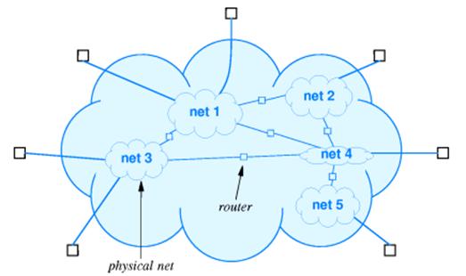
An Overview
of the Internet
The
global Internet is best seen as a mechanism that allows computers to
communicate.
The
Internet is a collection of interconnected networks, each with its own
protocol.
It provides the illusion of a single network, but has considerable internal
structure.
For our purposes, we shall
divide networks into two general classes:
1. Local
Area Networks (LAN)
2. Wide Area
Networks (WAN)
What Is
Connected to the Internet?
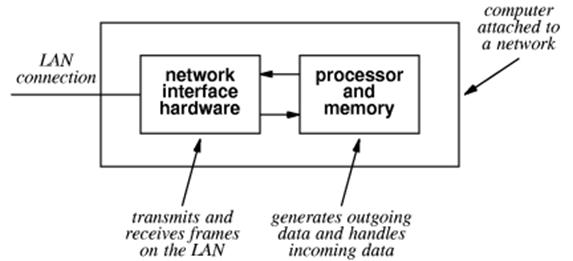
We
consider our computers to be connected to the Internet.
Technically,
it is the NIC (Network Interface Card) that is connected. This is connected
to a LAN (Local Area Network) that itself is connected to the Internet via a router.
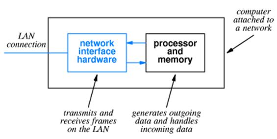
The
Network Interface Card is an Input / Output device attached to the computer.
It
communicates with the computer using Direct Memory Access (DMA).
The
physical network address, called MAC address (for Media Access Control)
address,
is a 48–bit address that identifies the NIC, not the computer.
Attaching a
Computer to a Local Area Network
This
is a typical attachment that uses the original (Thicknet) wiring.
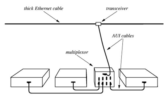
A
number of devices in a single room would be connected through a multiplexor to
the
cable (called an “Ethernet cable”, after its protocol) through a transceiver
(called an
“AUI” for “Attachment Unit Interface”)
The AUI was typically placed
above a false ceiling, making it hard to locate and repair
a malfunctioning unit.
Attaching a
Computer to a LAN (Part 2)
Current
technology for attaching computers to a network uses a technology called
twisted pair wiring. Names for this wiring include “10BaseT” and
“100BaseT”.
The
twisted pair cable attaches to the NIC through a RJ–45 connector.
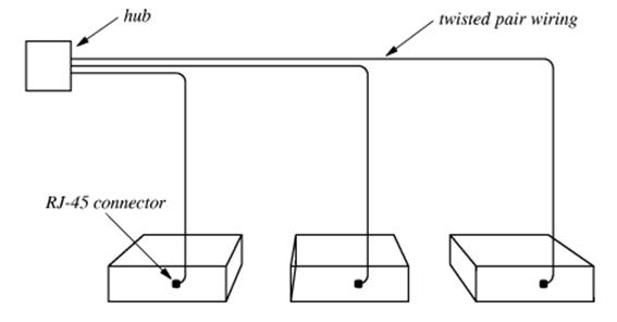
The
hub connects these computers to the
larger network.
The mathematicians in the
class will note that this is a star topology and not the expected
ring topology, supposedly used for networks.
It is treated as if it were a ring.
Typical
Group Setup for Twisted–Pair Networks
Here
is a typical group setup in which a number of computers are connected to the
Internet through a hub.
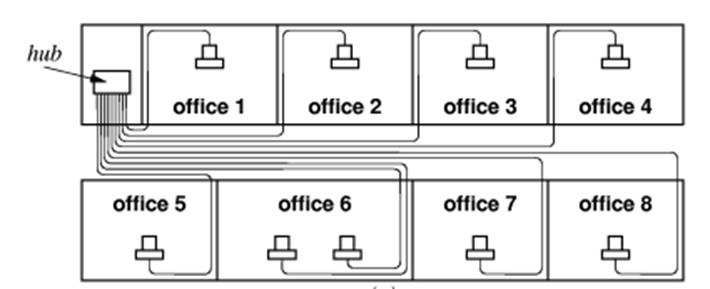
The
hub is often contained in a “network
closet”, which is a small locked room.
This
facilitates maintaining and securing the network assets.
The
only part of the network above the ceiling is a collection of twisted–pair
wires,
which are usually quite reliable. In any
case they are easy and cheap to replace.
Addressing
the NIC
Each
computer on a LAN is addressed using the MAC (Media Access Control) address
of its NIC (Network Interface Card).
The
MAC address is a 48–byte address, written as six bytes or twelve hexadecimal
digits.
We
show two typical MAC addresses;
00:20:C5:00:5F:C1 often written as
EagleTec_00:5F:C1
00:40:05:3C:3D:8B often written as AniCommu_3C:3D:8B
MAC
address assignment is coordinated by the IEEE.
Each manufacturer of NIC’s
is allocated blocks of 224 addresses (three bytes). In the above, we see that
Eagle Tec has been allocated the block
of addresses beginning with 00:20:C5,
Affinity Communications has been
allocated the block beginning with 00:40:05.
Remember
that each block of 224 addresses allows a manufacturer to produce 224
(16, 777, 216) network interface cards with unique addresses.
It
is likely that the major manufacturers have two or more blocks of MAC addresses
assigned to them.
IP Addresses
and MAC Addresses
In discussing the Internet, we normally use 32–bit IP
addresses and not 48–bit MAC
addresses. For the examples discussed
above, we have:
MAC Address 00:20:C5:00:5F:C1 IP Address 130.57.20.10
MAC Address 00:40:05:3C:3D:8B IP Address 130.57.20.1
The
IP addresses are used for communication over the global Internet.
The
MAC addresses are used for communication over the LAN.
The
router that connects the LAN to the global Internet handles translation between
the two forms of addresses.
As
each client joins the LAN, it broadcasts its MAC address to all others on the
LAN.
The router detects this
broadcast, and replies with a message assigning an IP address
to the new client. The router then
handles the translation.
Structure of
an IP Address
Technically,
we are discussing the structure of an IP–v4 (IP, version 4) address.
This
is a 32–bit number, represented as four groups in a dotted decimal notation.
Consider
the IP address 168.192.250.3.
Note
that each of these four numbers will be in the range 0 through 255 inclusive;
in other words, it can be represented as an eight–bit binary number.
Decimal
168 = 0xA8
Decimal
192 = 0xC0
Decimal
250 = 0xFA
Decimal
3 = 0x03
So
IP address 168.192.250.3 can be
written as 0xA8 C0 FA 03
It
can be written in binary as 1010
1000 1100 0000 1111 1010 0000 0011
It
can also be written as a single decimal number 2
831 219 203
The
dotted decimal notation is generally agreed to be the easiest to use.
The Domain
Name System
The
DNS (Domain Name System) allows us to use the mnemonic hostnames to the IP
addresses that are required by the IP network layer.
Typical
mnemonic hostnames include:
www.colstate.edu
www.csna.org
The
hierarchy of the hostnames is from right to left, with the part on the right
denoting
the high–level group to which the address belongs. Some high–level domains are:
.com commercial firms within the
United States (usually)
.edu educational
institutions
.mil organizations and branches of
the U.S. Department of Defense
.org non–profit organizations
The
last two parts of this address are “owned” by a specific organization.
Any
hostname address ending in “colstate.edu” will belong to Columbus State
University
Examples
of this are www.colstate.edu, cs.colstate.edu, csc.colstate.edu,
lsm.colstate.edu
PING
Pinging
www.colstate.edu [168.26.193.117] with 32 bytes of data:
Reply
from 168.26.193.117: bytes=32 time<1ms TTL=127
Reply
from 168.26.193.117: bytes=32 time<1ms TTL=127
Reply
from 168.26.193.117: bytes=32 time<1ms TTL=127
Reply
from 168.26.193.117: bytes=32 time<1ms TTL=127
Ping
statistics for 168.26.193.117:
Packets: Sent = 4, Received = 4, Lost = 0
(0% loss),
Approximate
round trip times in milli-seconds:
Minimum = 0ms, Maximum = 0ms, Average = 0ms
Pinging
csna.org [67.63.199.206] with 32 bytes of data:
Reply
from 67.63.199.206: bytes=32 time=48ms TTL=41
Reply
from 67.63.199.206: bytes=32 time=52ms TTL=41
Reply
from 67.63.199.206: bytes=32 time=54ms TTL=41
Reply
from 67.63.199.206: bytes=32 time=50ms TTL=41
Ping
statistics for 67.63.199.206:
Packets: Sent = 4, Received = 4, Lost = 0
(0% loss),
Approximate
round trip times in milli-seconds:
Minimum = 48ms, Maximum = 54ms, Average =
51ms
The TCP/IP
Protocol Stack
A
protocol stack divides the process of communication into several logical
layers. The
TCP/IP protocol calls for five logical layers.
We list them from highest to lowest level.
Application at this
level, we are dealing with applications such as e–mail, web
browsing, file
transfer, etc.
Logically,
we have two applications directly communicating.
Transport this
layer provides communication between two applications,
probably on
different computers.
This
level uses IP addresses and port numbers.
Network this
layer provides communication between two computers,
probably on
different Local Area Networks.
This
level uses IP addresses.
Link this
layer provides communication between two computers
on the same
Local Area Networks.
This
level uses MAC addresses.
Physical this
layer provides for actual transport of bits over either an
electrical
network or an optical fiber network.
Connection–Oriented
vs. Datagram Networks
The
Internet is a bit unusual in that it is not a connection–oriented network.
The
U.S. telephone network is the best example of a connection–oriented network.
One
dials a phone number, establishes a connection, and then keeps that connection
open for the duration of the conversation.
This might include a lot of time “on hold”.
Most
networks break the messages and other data being passed into a number of packets,
also called “datagrams”. Each packet can be routed independently from
the source to
the destination, leading to a great flexibility in the network.
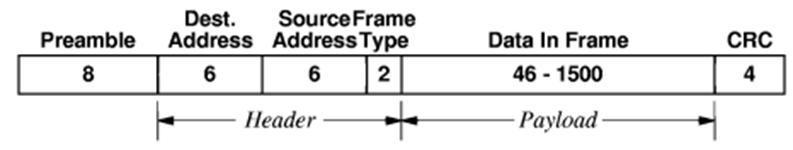
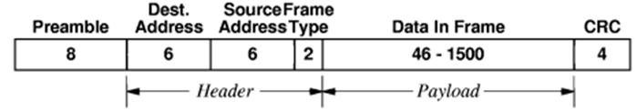
At
the physical level, a packet is embedded in an Ethernet frame as the frame payload.
It has s 48–bit MAC address for the source node and destination node, a frame
type,
and a CRC for error detection. For IP
version 4, the frame type is 0x0800.
The IP
(Internet Protocol)
The
current version is IP, version 4. The
next version will be called IP, Version 6.
It was originally called “IP – the Next Generation”. Guess why?
IP
is responsible for communication between computers. It does not connect
applications on those computers, as do the next few protocols.
An
IP datagram will be placed within an Ethernet frame for transmission over the
net.
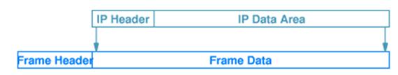
Remember
that the frame header has a flag set to 0x0800 for encapsulated IP.
The
IP header contains a protocol flag that indicates the datagram type.
Typical values are 1 ICMP (Internet
Control Message Protocol)
6 TCP (Transmission
Control Protocol)
17 UDP (User
Datagram Protocol)
End–to–End
Protocols
IP
connects computers, but cannot determine the true end points of a connection,
which must be two applications.
The
two major end–to–end protocols are TCP and UDP.
The
main difference between the two has to do with the reliability of the
communication.
TCP
is characterized by:
1. Reliable
transport. TCP guarantees that
the data sent across the connection
will be delivered exactly as sent,
with no data missing or out–of–order.
This implies retransmission of lost
packets and rearrangement of those that are
delivered out of order.
2. Connection
Oriented Although it uses
datagrams, TCP establishes a connection
between two applications that
persists for the duration of the session.
UDP
is characterized as a “best effort”
protocol, with no guarantees of packet delivery.
Consider
transmission of music over the Internet.
In this case, efficiency is important
and occasional dropped packets are only a minor nuisance.
More on the
NIC
As
noted above, the NIC is the unit that is actually attached to the network.
For
the attached computer, it acts as a DMA Input / Output device.
Each
NIC has a unique 48–bit MAC (Media Access Control) physical address.
These are designed to be globally unique, and are administered by the IEEE.
In
standard mode, a NIC scans frames
being sent on the network but stores only
those frames with its MAC address as a destination.
In
promiscuous mode, it will process any frame on the network. This is used by
devices, such as network sniffers,
used to diagnose networks or spy on them.
The NIC
Takes a Message
When
the NIC has copied an entire frame from the network, the I/O sequence follows
the
standard DMA process.
1. The NIC asserts an interrupt to the CPU.
2. The CPU sends an ACK to the NIC.
3. The NIC places its vector on the I/O data lines.
4. The interrupt handler uses the vector to
locate and start the interrupt handler
appropriate for the NIC.
5. The interrupt handler sends the NIC a byte
count (usually the Ethernet frame size)
and a starting physical address in
memory. It then commands the NIC to start
data transfer and assert an
interrupt when the input has been finished.
6. At the end of DMA, possibly due to an
error, the NIC again interrupts the CPU.
This interrupt is processed much
as above.
7. The operating system then examines the
frame to determine the type of
service to be associated with the
frame.
The O/S
Takes a Message
In
response to the “DMA done” interrupt issued by the NIC, the operating system
schedules the appropriate utility program to examine the frame.
This
utility extracts the frame type, and determines that it is 0x0800.
The
frame type indicates that the payload is an IP version 4 datagram.
The
O/S interrupt handler cannot call IP directly.
It places the payload into a
dedicated message queue and then uses a message passing primitive to signal IP.
Note
that the term “IP” is used in two contexts
1. The
protocol dictating how the computers will communicate, and
2. The
actual software that implements that protocol.
IP Takes a
Message
When
the IP program processes the datagram, it extracts the service type from the
IP header. The IP header has quite a few
fields, shown in this figure.
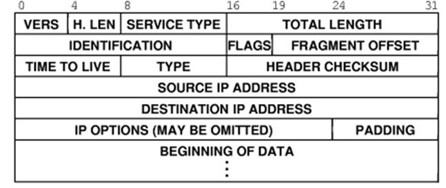
The
version number will be either 4 or 6 for the next little while.
The protocol type is stored in the field called
“TYPE”. It has one of several values:
1 ICMP
6 TCP
17 UDP
Protocol
Ports
Each
of UDP and TCP is an end–to–end protocol; that is, it connects two application
programs (presumably of the same type).
The
standard way of identifying an application is known as a protocol port.
For
example, the application to handle HTTP will associate itself with protocol
port 80.
Thus, a datagram will come to the computer with the message “I am a HTTP
packet,
please route me to whatever application processes HTTP”.
All
protocol ports are defined to be 16–bit unsigned integers; 0 to 65,535
inclusive.
The
first 1, 024 ports (numbered 0 through 1, 023) are defined as well–known protocol
ports, defined by a standard called
RFC 793.
Some of the well–known protocol port numbers are as
follows.
20 FTP File
Transport Protocol Data
21 FTP File
Transport Protocol Control
23 Telnet
25 SMTP Simple
Mail Transfer Protocol
53 DNS Domain
Name System
80 HTTP Hypertext
Transfer Protocol
TCP Takes A
Message
Suppose
that IP determines that the datagram contains a TCP packet.
TCP
calls the packet a segment.
Here
is the format of a TCP header.
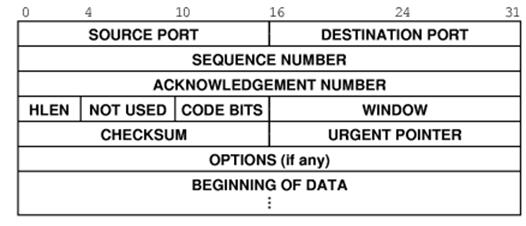
TCP
processes this header, extracting the destination port and determining the
application to receive the data contained in the segment.
TCP
then places the segment in the appropriate queue and uses an operating system
primitive called a “semaphore” to signal the application that it has data.