To
motivate our discussion of binary addition, let us first look at decimal
addition. Consider
the sum 15 + 17 = 32. In the standard
form in which most of us learned addition, the problem
would be stated as follows:
15
+ 17
32
First, note that 5 + 7 = 12. In order to speak of binary addition, we must
revert to a more basic
way to describe 5 + 7; we say that the sum is 2 with a carry-out of 1. Consider the
sum 1 + 1,
which is known to be 2. However, the
correct answer to our simple problem is 32, not 22,
because in computing the sum 1 + 1 we must consider the carry-in digit, here a 1.
With that in
mind, we show two addition tables – for a half-adder and a full-adder. The half-adder table is
simpler as it does not involve a carry-in.
The following table considers the sum and carry from
A + B.
Half-Adder A + B
A B Sum Carry
0 0 0 0 Note
the last row where we claim that 1 + 1 yields a
0 1 1 0 sum
of zero and a carry of 1. This is
similar to the
1 0 1 0 statement
in decimal arithmetic that 5 + 5 yields a
1 1 0 1 sum
of 0 and carry of 1 when 5 + 5 = 10.
Remember that when the sum of two numbers equals or exceeds
the value of the base of the
numbering system (here 2) that we decrease the sum by the value of the base and
generate a
carry. Here the base of the number
system is 2 (decimal), which is 1 + 1, and the sum is 0.
Say “One plus one equals two plus zero: 1 + 1 = 10”.
For us the half-adder is only a step
in the understanding of a full-adder, which implements
binary addition when a carry-in is allowed.
We now view the table for the sum A + B, with a
carry-in denoted by C. One can consider
this A + B + C, if that helps.
Full-Adder: A + B with Carry
A B C Sum Carry
0 0 0 0 0
0 0 1 1 0
0 1 0 1 0
0 1 1 0 1
1 0 0 1 0
1 0 1 0 1
1 1 0 0 1
1 1 1 1 1
As
an example, we shall consider a number of examples of addition of four-bit
binary
numbers. The problem will first be
stated in decimal, then converted to binary, and then
done. The last problem is introduced for
the express purpose of pointing out an error.
We
shall see in a minute that four-bit binary numbers can represent decimal
numbers in the
range 0 to 15 inclusive. Here are the
problems, first in decimal and then in binary.
1) 6
+ 1 0110 + 0001
2) 11
+ 1 1011 + 0001
3) 13
+ 5 1101 + 0101
0110
1011 1101 In the
first sum, we add 1 to an even number.
This
0001 0001 0101 is quite easy to do.
Just change the last 0 to a 1.
0111
1100 0010 Otherwise,
we may need to watch the carry bits.
In the second sum, let us proceed from right to left. 1 + 1 = 0 with carry = 1. The second
column has 1 + 0 with carry-in of 1 = 0 with carry-out = 1. The third column has 0 + 0 with
a carry-in of 1 = 1 with carry-out = 0.
The fourth column is 1 + 0 = 1.
Analysis of the third sum shows that it is correct bit-wise
but seems to be indicating that
13 + 5 = 2. This is an example of
“busted arithmetic”, more properly called overflow.
A give number of bits can represent integers only in a given range; here 13 + 5
is outside
the range 0 to 15 inclusive that is proper for four-bit numbers.
Back to the Half–Adder
The half–adder may be seen as adding the units column in
integer addition; there is no
carry–in. As we shall see later, it is
often convenient to replace a half–adder with a full–adder
in which the carry–in is set to 0. The
two are equivalent. Here again is the
truth table.
|
A |
B |
Sum |
Carry |
|
0 |
0 |
0 |
0 |
|
0 |
1 |
1 |
0 |
|
1 |
0 |
1 |
0 |
|
1 |
1 |
0 |
1 |
What the
last row says is simple. In decimal, 1 +
1 is 2. But 2 is the basis of the binary
system,
so we have to say that 1 + 1 = 1·21 + 0·20; in other words, the sum is 0 and the
carry–out is 1.
This is similar to what might be said in decimal arithmetic; 5 + 5 is really
10, but we might say
that the sum is 0 and the carry–out is 1,
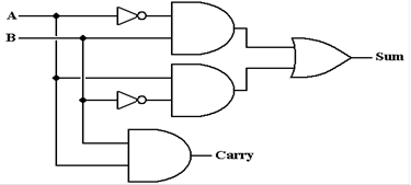
The simplest circuit implementation of a half–adder involves
an AND gate and a XOR gate.
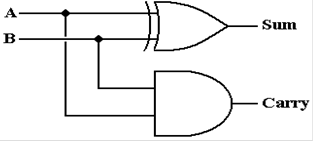
An equivalent implementation is shown in order to facilitate
discussion of the full–adder.
Back to the Full–Adder
The full–adder might be seen as equivalent to the tens or
hundreds column in standard addition;
there must be provision for a carry–in from the column to the right. Here again is the truth table
for the full adder with an additional column giving comments.
|
A |
B |
Cin |
Sum |
Cout |
Result = 2 · Cout + 1 · Sum |
|
0 |
0 |
0 |
0 |
0 |
0
= 2 · 0 + 1 · 0 |
|
0 |
0 |
1 |
1 |
0 |
1
= 2 · 0 + 1 · 1 |
|
0 |
1 |
0 |
1 |
0 |
1
= 2 · 0 + 1 · 1 |
|
0 |
1 |
1 |
0 |
1 |
2
= 2 · 1 + 1 · 0 |
|
1 |
0 |
0 |
1 |
0 |
1
= 2 · 0 + 1 · 1 |
|
1 |
0 |
1 |
0 |
1 |
2
= 2 · 1 + 1 · 0 |
|
1 |
1 |
0 |
0 |
1 |
2
= 2 · 1 + 1 · 0 |
|
1 |
1 |
1 |
1 |
1 |
3
= 2 · 1 + 1 · 1 |
A bit of
Boolean algebra will show that the Sum and Carry (out) can be represented as:
![]()
A bit more
Boolean algebra will result in the following simplification of the second
expression.
![]()
Here is the circuit implementing these two expressions.
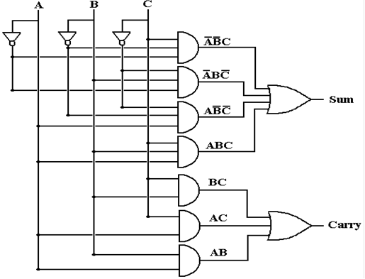
This is the standard implementation of a full–adder. There is another worth mention.
This second implementation of a full–adder appears in the
text by Rob Williams. It uses two
half–adders and an OR gate. Here is the
circuit.
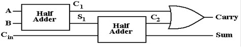
First, we must show that the circuit does indeed function as
a full–adder. This is done
using a truth table. Note a column for
each intermediate result. This is a
full–adder.
|
A |
B |
Cin |
C1 |
S1 |
C2 |
Carry |
Sum |
|
0 |
0 |
0 |
0 |
0 |
0 |
0 |
0 |
|
0 |
0 |
1 |
0 |
0 |
0 |
0 |
1 |
|
0 |
1 |
0 |
0 |
1 |
0 |
0 |
1 |
|
0 |
1 |
1 |
0 |
1 |
1 |
1 |
0 |
|
1 |
0 |
0 |
0 |
1 |
0 |
0 |
1 |
|
1 |
0 |
1 |
0 |
1 |
1 |
1 |
0 |
|
1 |
1 |
0 |
1 |
0 |
0 |
1 |
0 |
|
1 |
1 |
1 |
1 |
0 |
0 |
1 |
1 |
A simple
way to confirm that this is the truth table of a full–adder is to count the
number of
1’s in the triple (A, B, Cin). If the count is odd (1 or 3) the sum is 1,
otherwise the sum is 0.
If the count is 2 or more, the carry is 1, otherwise the carry is 0.
The Complete Full–Adder
We have just considered a full adder for two one–bit numbers
with a carry–in (from somewhere).
We now extend the idea to multiple bit binary numbers. Typical examples include 8, 16, 32, and
64 bit numbers. Our example will focus
on four bit numbers. We add two four bit
numbers
(A3, A2, A1, A0) and (B3,
B2, B1, B0).
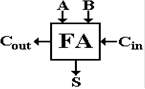
We begin with the block diagram of a full–adder. Following standard practice in the study of
computer organization and architecture, once the inner details of a circuit
have been mastered,
we no longer show them, but show the circuit as a single block.
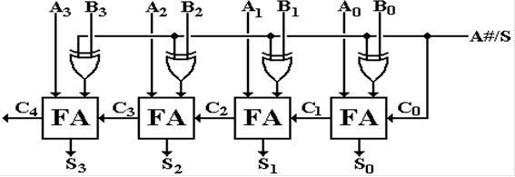
We now extend this design to a four–bit parallel adder. This design is the logical basis for the
adder in a modern ALU. It is too slow
for actual use.
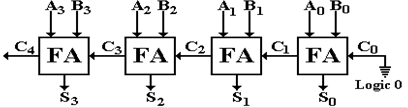
Recall that the “units bit” addition with A0 and
B0 could have been implemented as a
half–adder. For reasons that will appear
shortly, this was implemented as a full–adder
with the carry input tied to logic 0, here 0 volts (represented by the ground
symbol).
This is called a “ripple carry” adder in that the carry bit
ripples from right to left. Each
full–adder has a time delay before the carry–out bit is valid. Consider FA1, the one with inputs
A1, B1, and C1. The input C1 does not become valid until some
time after the inputs to FA0,
A0 and B0 become valid.
Another delay ensues before the outputs S1 and C1
are valid.
For details on the timing of a full–adder and a ripple carry
adder, please refer to this author’s
textbook on Computer Architecture.
Binary
Subtraction
We shall use a full–adder to perform binary subtraction by
following the standard rule from
arithmetic: A – B = A + (–B). We just
need to negate one of the inputs to the full–adder and
we have a subtractor. How do we do that?
All modern Arithmetic Logic Units implement integer
arithmetic using the two’s–complement
form. Thus we need to build a two’s–complement
negator. As an aside, we note that it is
possible to build an adder/subtractor for other formats, but that these designs
are quite complex.
It is the simplicity of the standard two’s–complement unit that lead to its
being the standard.
Remember the rule for negating an
integer in two’s–complement arithmetic: take the
one’s–complement and add one. As an
expression, this is as follows:
![]()
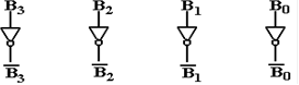
But recall that taking the one’s–complement of a binary
number is exactly the same as taking
the logical NOT of each of its bits.
Here is the case for the 4–bit number B3B2B1B0. We begin
with a circuit to produce the one’s–complement of the number.
In order to get the negative of the number, all we need to
do is add 1 to it. Of the several ways
this could be done, the best way is to set the carry–in of the units full–adder
to 1.
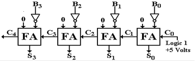
Consider the following positive 4–bit number. B = 0100
Take the one’s complement to get this number 1011
Add one to the number to get the true negative 1100
If the left input to each FA had been the bit values of A,
we would have (A – B). Now we
try to convert this into a unit that will add or subtract.
In order to build the unit, we need a circuit element that
can generate either the plain version
of its input or the one’s–complement of its input. But we have exactly that in the XOR
gate.
Here is the truth table for the XOR circuit, with two inputs: B and S (select).
|
B |
S |
B
Å S |
|
0 |
0 |
0 |
|
1 |
0 |
1 |
|
0 |
1 |
1 |
|
1 |
1 |
0 |
Given the
above, here is the full circuit for the 4–bit adder/subtractor.
Consider
the case when A#/S = 0. This indicates
that addition is to take place. This
signal
is fed into the exclusive OR gates feeding the right inputs of the adders,
passing the plain form
of the B input. This feeds the units
carry–in; the result is A + B + 0, or just A + B.
Now
consider the case when A#/S = 1. This
indicates that subtraction is to take place.
This
is fed into the exclusive OR gates, passing the one’s complement of B into the
right inputs of
the adder. The signal feeds the units
carry–in, thus the result we get is
![]() .
.
Consider the following example of addition and
subtraction. In decimal, the numbers are
A = 5 and B = 2. It should be obvious
that A + B = 7 and A – B = 3.
Let’s do the arithmetic in 4–bit binary. The addition is straightforward.
A = 0101
B = 0010
Sum = 0111
In order to evaluate A – B, it is necessary first to take
the two’s–complement of B.
B =
0010
1’s complement = 1101
Add 1 to get = 1110
Here then is the addition to get A – B
A 0101 In
the 4’s column, 1 + 1 with carry–in = 0 is 0, with carry–out = 1.
–B 1110 In the 8’s column, 1 + 0 with carry–in = 1 is 0, with
carry–out = 1
0011 The carry out from the 8’s column is discarded.
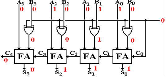
Here is the circuit above when addition is called for; A#/S
= 0. Note that the selector input
to the exclusive OR function is a 0, so that the B values are passed unchanged.
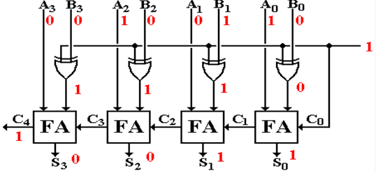
Here
is the circuit above when subtraction is called for; A#/S = 1. The selector input to
the exclusive OR function is a 1, so that the value passed is the
one’s–complement of B
As indicated above, these circuits are correct logical
models of an adder/subtractor, but
they are not actually used. Consider a
32–bit version of this ripple carry adder.
It would
have 32 full adders, connected in the same manner as above.
Such a ripple carry adder is much too slow for commercial
use. Each full–adder must wait on
the completion of the carry–out calculations of all the full–adders to its
right before it can
begin calculating the sum and carry–out.
The full–adder for the sign bit (FA 31) must wait for all 31
full–adders (FA 0 to FA 30) to
its right to complete their calculations before starting. That is a long wait.
The
Shifter
Bits in an addressable unit, such as a byte or word, are
considered to have position. A shifter
shifts each bit in the unit by a fixed amount, with variations depending on
type.
In our examples of shifting, we shall consider 8–bit bytes.
The term “byte”, coined by IBM, and
long thought to be trademarked by them, was chosen for the unit of storage
appropriate to store
the binary coding for a character. At
the time, the complete IBM character set required seven
bits to encode; this was extended to 8 bits out of habit.
Each byte, having eight bits, has its bits numbered from 0
through 7. Here is the bit numbering
scheme used by all manufacturers except IBM.
|
Bit
# |
7 |
6 |
5 |
4 |
3 |
2 |
1 |
0 |
|
Value |
1 |
0 |
0 |
1 |
0 |
1 |
1 |
0 |
Bit 7 is
the most significant bit; bit 0 is the least significant bit. In hexadecimal notation, this
would be represented as 96. The unsigned
decimal value is 9·16
+ 6 = 150.
Here are some examples of simple logical shifts, in which a
0 is shifted into the vacated “spot”.
The original value in binary: 1001 0110
The original value right shifted one place: 0100 1011
The original value right shifted two
places 0010 0101
The original value in binary: 1001 0110
The original value left shifted one place: 0010 1100
The original value left shifted two
places 0101 1000
There is some interesting arithmetic for unsigned integers
hidden in these shift operators. It is
more easily noticed for smaller numbers.
Decimal 11 in binary is 0000
1011.
The original value in binary: 0000 1011,
decimal value = 11
The original value shifted right one place 0000 0101, decimal value = 5
The original value shifted right two places 0000 0010, decimal value = 2.
The original value in binary: 0000 1011,
decimal value = 11
The original value shifted left one place 0001 0110, decimal value = 22
The original value shifted left two places 0010 1100, decimal value = 44.
In other words, for unsigned binary integers, a single left
shift is equivalent to multiplication by
two, and a single right shift is equivalent to division by two, with the
remainder discarded. For
signed binary integers, the situation is only slightly more complicated. The shift operations are
much more time efficient than either integer multiplication or integer
division. For this reason,
one often sees shift operations substituted for multiplications and divisions
by powers of two.
The hardware for the simplest shift units shifts only one
place at a time. To shift left by three
places requires three calls to the shift operator. There are two types of shifters that are more
efficient and hence more complex. The
logarithmic shifter has a number of stages that is the
logarithm (base 2) of the number of bits; a shifter for 16 bits would have four
stages (16 = 24),
and a shifter for 32 bits would have five stages (32 = 25).
The most efficient shifter is the barrel shifter; it has one stage only.
In general, there are two types of shifts – left shifts and
right shifts. These names correspond
roughly to the way in which we would illustrate these shifts by drawing
diagrams. Each of the
two shift types comes in three varieties: logical, circular, and arithmetic.
The basic definition of each shift type is in terms of
shifting by one place. We should note
that
multiple shifts are easily defined; shifting by N places must be equivalent to
N single shifts. For
convenience in designing a barrel shifter, we normally think in terms of
shifting by N = a power
of two, so that a shift by 13 places is a shift by 1 place, followed by a shift
by 4 places, and then
a shift by 8 places, as 13 = 1 + 4 + 8.
We shall illustrate the shift types by considering them as
applied to an eight-bit shift register,
with contents labeled as R7 R6 R5 R4 R3
R2 R1 R0. We use 1001 0110 as an example.
Logical
Shifts
Logical shifts just move bits in the
indicated direction, padding out with 0’s.
Shifts can be by
any count, but shifts by more than the size of the register leave it all 0’s.
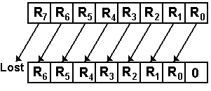 For left shifting an N-bit register by 1 place
RJ+1 ¬ RJ for
0 £ J < (N – 1)
R0 ¬ 0, R(N – 1) is lost
As an example of a shift of an 8-bit
register
For a single left shift 1001
0110 becomes 0010 1100
Left shift by 2 places: 1001
0110 becomes 0101 1000
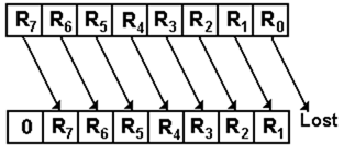 For right shifts by 1 place
RJ+1 ® RJ for
0 £ J < (N – 1)
R(N – 1) ¬ 0, R0 is lost
As an example of a 8-bit register
shift
For a single right shift 1001 0110 becomes
0100 1011
Right shift by 2 places: 1001
0110 becomes 0010 0101
Note that shifting either left or right by eight or more
places produces the result 0000 0000,
so that the shift count will normally be in the range 0 through 7 inclusive.
The general rule for an N-bit register is that the shift
count is usually in the range from
0 to (N – 1) inclusive, a modulo–N non–negative number.
Arithmetic
Shifts
Arithmetic shifts are identical to logical shifts except
that the sign bits are preserved.
Arithmetic
shifting is normally defined only for right shifts.
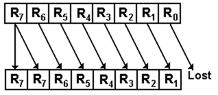
For right shifts by 1 place
RJ+1 ® RJ for
0 £ J < (N – 1)
R(N – 1) ® R(N – 1), R0 is lost
As an example of an 8-bit register 1001 0110 becomes 1100 1011
The purpose of arithmetic shifts is to cause the right shift
to become equivalent to division by
two on two’s-complement integers. We use
8-bit two’s-complement arithmetic to illustrate the
correspondence of shifting to multiplication and division. The range of this representation is
from – 128 to 127 inclusive.
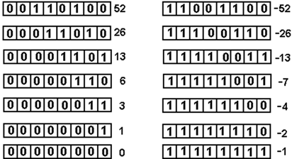
Consider the number 52, represented as 0011 0100 in
binary. Taking the two’s-complement
of this binary pattern, we find that the representation of – 52 is 1100 1100.
We first apply successive arithmetic right shifts to both 52
and – 52.
We now
apply successive logical left shifts to the same two numbers.
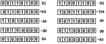
Note that
this corresponds to multiplication by two whenever the sign bit stays the same.
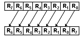
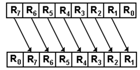
Circular
Shifts
Circular shifts are identical to
logical shifts except that bits “shifted off” one end are put at the other end,
thus making the shift appear as a circle.
For left shifts by 1 place
RJ+1 ¬ RJ for
0 £ J < (N – 1) R0 ¬ R(N – 1), nothing is lost
As an example for an 8-bit shift
1001 0110 becomes 0010 1101
For right shifts by 1 place
RJ+1 ® RJ for
0 £ J < (N – 1)
R(N – 1) ¬ R0
As an example of an 8-bit shift
1001 0110 becomes 0100 1011
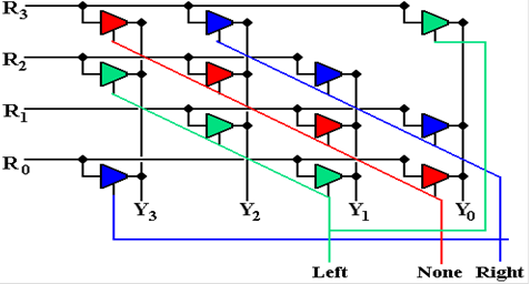
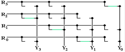
The Barrel Shifter
To give a flavor of a barrel shifter, I design a single bit
circular shifter for a 4–bit number.
We must begin with a table giving the output of the shifter in terms of the
input R3R2R1R0.
|
|
No
shift |
Left
Circular |
Right
Circular |
|
Y3 |
R3 |
R2 |
R0 |
|
Y2 |
R2 |
R1 |
R3 |
|
Y1 |
R1 |
R0 |
R2 |
|
Y0 |
R0 |
R3 |
R1 |
Here is
the circuit. It is implemented with
tri–state buffers. When there is no
shift, the red line
is asserted. The green line is asserted
for a single left shift and the blue line for a right shift.
As complex
as the above circuit appears to be, it can grow much messier for reasonably
sized
shift units. The number of tri–state
buffers scales quadratically as the number of bits in the
ALU; more specifically a shifter for an N–bit ALU would require 3N2
tri–states. That would
be 768 tri–states for a 16–bit ALU and 3,072 tri–states for a 32–bit ALU.
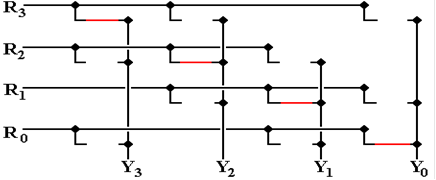
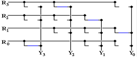
In order
to clarify the above circuit, we present the state of the circuit for each of
the three shift
options: no shift, left shift by 1, and right shift by 1. Note that for each diagram, each input line
is connected to precisely one output line.
First the
no shift option. The lines in red show
the connections. Other wires are not
connected.
Now
the left shift option. The lines in
green show the connections.
And
now the right shift option. The lines in blue show the connections.
Multiplication
and Division
We note immediately that
multiplication of two N–bit integers yields a product with 2N bits. For
that reason, we shall discuss N–bit multiplication with a 2N–bit product, and
N–bit division with
a 2N–bit dividend, an N–bit divisor, an N–bit quotient, and N–bit
remainder. This “doubling of
the digits” is seen in decimal as well as binary multiplication.
Decimal: 9,999 ·
9,999 = 99,980,001
Binary 1111 · 1111 = 1110 0001 (15 · 15 = 225)
The most common implementations of
multipliers call for two 16–bit numbers with a 32–bit
product, and two 32–bit numbers with a 64–bit product.
We begin with a consideration of
multiplication for unsigned positive integers.
At one level, this
is quite simple, as the “times table” is very small. Here it is.
|
A |
B |
A·B |
|
0 |
0 |
0 |
|
0 |
1 |
0 |
|
1 |
0 |
0 |
|
1 |
1 |
1 |
One might note that this is exactly the truth table for the
logical AND function, which is denoted
by the same symbol as multiplication.
This might suggest the use of the logical AND gate in a
multiplier; the true circuits are even simpler.
Consider a labeled example.
1011 the multiplicand, with
decimal value 11
1001 the
multiplier, with decimal value 9
1011
0000
0000 the four partial products
1011___
1100011 the product, with decimal value 99
Note that there are four partial
products, one for each bit in the multiplier.
Each partial product
is the length of the multiplicand, and is either a copy of the multiplicand or
all 0. The standard
assumption is that the multiplicand and multiplier have equal length, each
having the length of
the standard integer in the architecture.
All commercial designs allow different lengths for
integer representations (8–bit, 16–bit, 32–bit, etc.), providing a number of
distinct multiplication
operations (8–bit by 8–bit, 16–bit by–16 bit).
Modern multiplication algorithms are
based on shifting and adding. This
allows one to use the
minimum number of registers required to hold the operands and the results. The standard
approach calls for setting up a result of 2N bits, initialized to zero. The multiplier is then
examined right to left. If the bit is 1,
the multiplicand is added to the result.
If not, nothing
is added.
The next step is to shift the
multiplicand left by one, and consider the next bit in the
multiplier. We illustrate this algorithm
with two 4–bit numbers and an 8–bit product.
For this example, label the
multiplier bits as M3M2M1M0; M3
= 0, M2 = 1, M1 = 1, M0 = 1.
For 4–bit multiplication, we initialize the register set used for the product
to eight 0’s.
At the start, the situation is as
follows. Multiplicand 1011
Results 00000000
M0 = 1, add multiplicand
to results Multiplicand 1011
Results 00001011
Shift the results register set right Multiplicand 1011
Results 00001011
M1 = 1, add multiplicand
to results Multiplicand 1011
Results 00100001
Shift the results register set right Multiplicand 1011
Results 00100001
M2 = 1, add multiplicand
to results Multiplicand 1011
Results 01001101
Shift the results register set right Multiplicand 1011
Results 01001101
M3 = 0, do not add. Multiplicand 1011
Results 01001101
Division
Standard division follows the same strategy as classical
long division, except that it cannot
use any human–style inspection to compare two numbers. The only way for an ALU to
compare two numbers is to perform a subtraction and test the sign of the
result. Here we shall
describe a variant of division called “restoring
division”, by which we mean that a subtraction
will be performed and, if the result is negative, the original value will be
restored by an addition.
Consider the manual algorithm as
applied to unsigned binary division. We
shall apply long division
to apply the divisor 1011 (decimal 11) to the dividend 10010011 (decimal
147). In the manual algorithm,
we place the divisor immediately below the dividend, test if it is too large,
and proceed accordingly.
_________
1011 )10010011
1011
At this point, a human would note that the divisor is larger
than the 4–bit part of the dividend
immediately above it and move on. The
ALU will perform the subtraction, get 1110 (or
minus 2), then add back the 1011 to get 1001, and only then move on.
Now the five–bit part of the dividend,
10010, is compared to the four–bit divisor, 1011, and
subtracted from it. A “1” is written directly above the units column for the
divisor.
_00001___
1011 )10010011
1011
0111
Next a 0 is “brought down”, the
divisor shifted once more to the right, and compared. The
divisor is smaller than the partial remainder.
The subtraction is performed.
_000011__
1011 )10010011
1011
01110
1011
0011
We now finish the division using the
standard manual practice.
_00001101
1011 )10010011
1011
01110
1011
001111
1011
100