The Idea of Ground
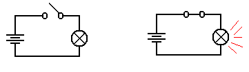
Consider
the above circuit, which suggests a two-wire design: one wire from the battery
to
the switch and then to the light bulb, and another wire from the bulb directly
to the battery.
One should note that the circuit does not require two physical wires, only two
distinct paths
for conducting electricity. Consider the
following possibility, in which the flashlight has a
metallic case that also conducts electricity.
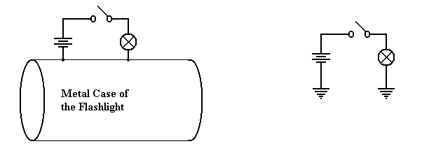
Physical
Connection Equivalent
Circuit
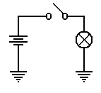
Consider the circuit at left, which shows
the physical connection postulated. When
the
switch is open, no current flows. When
the switch is closed, current flows from the battery
through the switch and light bulb, to the metallic case of the flashlight,
which serves as a
return conduit to the battery. Even if
the metallic case is not a very good conductor, there
is much more of it and it will complete the circuit with no problem.
In
electrical terms, the case of the battery is considered as a common ground, so that the
equivalent circuit is shown at right.
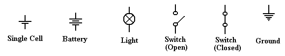
Note the new symbol in this circuit – this is the ground
element. One can consider all ground
elements to be connected by a wire, thus completing
the circuit. In early days of radio, the
ground was the metallic case of the radio – an
excellent conductor of electricity.
Modern automobiles use the metallic body of the car itself
as the ground. Although iron and steel
are not excellent conductors of electricity, the sheer
size of the car body allows for the electricity to flow easily.
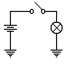
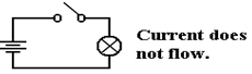
To conclude, the circuit at
left will be our representation of a
flashlight. The battery provides the
electricity, which flows through
the switch when the switch is closed, then through the light bulb, and
finally to the ground through which it returns to the battery.
As a convention, all switches
in diagrams will be shown in the open
position unless there is a good reason not to.
The student should regard the
above diagram as showing a switch which is not necessarily
open, but which might be closed in order to allow the flow of electricity. The convention of
drawing a switch in the open position is due to the fact that it is easier to
spot in a diagram.
Voltage, Current, and Resistance
It is now time to become a bit more precise in our discussion of
electricity. We need to
introduce a number of basic terms, many of which are named by analogy to
flowing water.
The first term to define is current,
usually denoted in equations by the symbol I. We all
have an intuitive idea of what a current is.
Imagine standing on the bank of a river and
watching the water flow. The faster the
flow of water, the greater the current; flows of water
are often called currents.
In the electrical terms, current is the
flow of electrons, which are one of the basic building
blocks of atoms. While electrons are not
the only basic particles that have charge, and are
not the only particle that can bear a current; they are the most common within
the context of
electronic digital computers. Were one
interested in electro-chemistry he or she might be
more interested in the flow of positively charged ions.
All particles have one of three basic
electronic charges: positive, negative, or neutral. Within
an atom, the proton has the positive charge, the electron has the negative
charge, and the
neutron has no charge. In normal life,
we do not see the interior of atoms, so our experience
with charges relates to electrons and ions.
A neutral atom is one that has the same number of
protons as it has electrons. However,
electrons can be quite mobile, so that an atom may gain
or lose electrons and, as a result, have too many electrons (becoming a
negative ion) or too
few electrons (becoming a positive ion).
For the purposes of this course, we watch only the
electrons and ignore the ions.
An electric charge, usually denoted by the symbol Q, is usually associated with a large
number of electrons that are in excess of the number of positive ions available
to balance
them. The only way that an excess of
electrons can be created is to move the electrons from
one region to another – robbing one region of electrons in order to give them
to another.
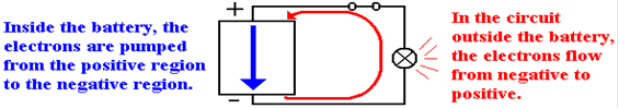
This is exactly what a battery does – it is an electron “pump” that moves
electrons from the
positive terminal to the negative terminal.
Absent any “pumping”, the electrons in the
negative terminal would return to the positive region, which is deficient in
electrons, and
cause everything to become neutral. But
the pumping action of the battery prevents that.
Should one provide a conductive pathway between the positive and negative
terminals of a
battery, the electrons will flow along that pathway, forming an electronic
current.
To clarify the above description, we
present the following diagram, which shows a battery, a
light bulb, and a closed switch. We see
that the flow of electrons within the battery is only a
part of a larger, complete circuit.
Materials are often classified by their
abilities to conduct electricity. Here
are two common
types of materials.
Conductor A conductor is a substance, such as copper or silver,
through which
electrons
can flow fairly easily.
Insulator An insulator is a substance, such as glass or wood,
that offers
significant
resistance to the flow of electrons. In
many of our
circuit
diagrams we assume that insulators do not transmit electricity
at
all, although they all do with some resistance.
The voltage is amount of pressure in the
voltage pump. It is quite
similar to water pressure in that it is the pressure on the electrons that
causes them to move through a conductor.
Consider again our
flashlight example.
The battery provides a pressure on the
electrons
to cause them to flow through the circuit.
When the switch is open,
the flow is blocked and the electrons do not move. When the switch
is closed, the electrons move in response to this pressure (voltage)
and flow through the light bulb. The
light bulb offers a specific
resistance to these electrons; it heats up and glows.
As mentioned above, different materials
offer various abilities to transmit electric currents.
We have a term that measures the degree to which a material opposes the flow of
electrons;
this is called resistance, denoted
by R in most work. Conductors have low resistance (often
approaching 0), while insulators have high resistance. In resistors, the opposition to the flow
of electrons generates heat – this is the energy lost by the electrons as they
flow through the
resistor. In a light bulb, this heat
causes the filament to become red hot and emit light.
An open switch can be considered as a
circuit element of extremely high resistance.
Summary
We have discussed four terms so far.
We now should mention them again.
Charge This refers to an unbalanced
collection of electrons. The term used
for denoting
charge is Q. The unit of charge is a coulomb.
Current This refers to the rate at which a
charge flows through a conductor.
The term used for
denoting current is I. The unit of current is an ampere.
Voltage This refers to a force on the electrons that causes them
to move. This force
can be due to a
number of causes – electro-chemical reactions in batteries
and changing magnetic
fields in generators. The term used for
denoting
voltage is V or E (for Electromotive
Force). The unit of current is a volt.
Resistance This is a measure of the degree to which a substance opposes
the flow of
electrons. The term for resistance is R. The unit of resistance is an ohm.
Ohm’s
Law and the Power Law
One way of stating Ohm’s law (named for Georg Simon Ohm, a German
teacher who
discovered the law in 1827) is verbally as follows.
The current that flows through a
circuit element is directly proportional to the
voltage across the circuit element and inversely proportional to the resistance
of that circuit element.
What that says is that doubling the
voltage across a circuit element doubles the current flow
through the element, while doubling the resistance of the element halves the
current.
Let’s look again at our flashlight
example, this time with the switch shown as closed.
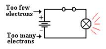
The chemistry of the battery is pushing
electrons away
from the positive terminal, denoted as “+” through the
battery towards the negative terminal, denoted as “–“.
This causes a voltage across the only
resistive element
in the circuit – the light bulb. This
voltage placed across the light bulb causes current to
flow through it.
In algebraic terms, Ohm’s law is easily
stated: E = I·R,
where
E is
the voltage across the circuit element,
I is
the current through the circuit element, and
R is
the resistance of the circuit element.
Suppose that the light bulb has a
resistance of 240 ohms and has a voltage of 120 volts
across it. Then we say E = I·R or
120 = I·240
to get I = 0.5 amperes.
As noted above, an element resisting the
flow of electrons absorbs energy from the flow it
obstructs and must emit that energy in some other form. Power is the measure of the flow of
energy. The power due to a resisting
circuit element can easily be calculated.
The power law is states as P = E·I,
where
P is
the power emitted by the circuit element, measured in watts,
E is
the voltage across the circuit element, and
I is
the current through the circuit element.
Thus a light bulb with a resistance of
240 ohms and a voltage of 120 volts across it has
a current of 0.5 amperes and a power of 0.5 · 120 = 60 watts.
There are a
number of variants of the power law, based on substitutions from Ohm’s
law.
Here are the three variants commonly seen.
P = E·I P
= E2 / R P =
I2·R
In our
above example, we note that a voltage of 120 volts across a resistance of 60
ohms
would produce a power of P = (120)2 / 240 = 14400 / 240 = 60 watts,
as expected.
The alert
student will notice that the above power examples were based on AC circuit
elements, for which the idea of resistance and the associated power laws become
more
complex (literally). Except for a few
cautionary notes, this course will completely ignore
the complexities of alternating current circuits.
Resistors
in Series
There are very many interesting combinations of resistors found
in circuits, but here we focus on only one – resistors in series;
that is one resistor placed after another.
In this figure, we
introduce the symbol for a resistor.
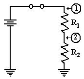
Consider the circuit above, with two
resistors having
resistances of R1 and R2, respectively. One of the basic laws of
electronics states that the resistance of the two in series is
simply the sum: thus R = R1 + R2. Let E be the voltage provided by the
battery. Then the
voltage across the pair of resistors is given by E, and the current through the
circuit elements
is given by Ohm’s law as I = E / (R1 + R2). Note that we invoke another fundamental law
that the current through the two circuit elements in series must be the same.
Again applying Ohm’s law we can obtain
the voltage drops across each of the two resistors.
Let E1 be the voltage drop across R1 and E2 be
that across R2. Then
E1
= I·R1
= R1·E
/ (R1 + R2), and
E2 = I·R2
= R2·E
/ (R1 + R2).
It should come as no surprise that E1 + E2 = R1·E / (R1 + R2)
+ R2·E
/ (R1 + R2)
=
(R1 + R2)·E / (R1 + R2) = E.
If, as is commonly done, we assign the
ground state as having zero voltage, then the voltages
at the two points in the circuit above are simple.
1) At point 1, the voltage is E, the full
voltage of the battery.
2) At
point 2, the voltage is E2 = I·R2 = R2·E /
(R1 + R2).
Before we present the significance of the
above circuit, consider two special cases.
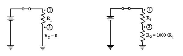
In the circuit at left, the second
resistor is replaced by a conductor having zero resistance.
The voltage at point 2 is then E2 = 0·E / (R1 + 0) =
0. As point 2 is directly connected to
ground, we would expect it to be at zero voltage.
Suppose that R2 is much bigger
than R1. Let R1 =
R and R2 = 1000·R. We calculate
the
voltage at point 2 as E2 = R2·E / (R1 + R2)
= 1000·R·E /
(R + 1000·R)
= 1000·E/1001,
or
approximately E2 = (1 – 1/1000)·E = 0.999·E. Point 2 is essentially at full voltage.
Putting
a Resistor and Switch in Series
We now consider an important circuit that is related to the above
circuit. In this circuit the
second resistor, R2, is replaced by a switch that can be either open
or closed.
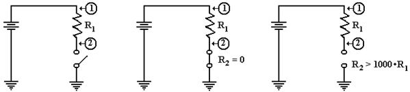
The Circuit Switch Closed Switch Open
The circuit of interest is shown in the
figure at left. What we want to know is
the voltage at
point 2 in the case that the switch is closed and in the case that the switch
is open. In both
cases the voltage at point 1 is the full voltage of the battery.
When the switch is closed, it becomes a
resistor with no resistance; hence R2 = 0. As we
noted above, this causes the voltage at point 2 to be equal to zero.
When the switch is open, it becomes
equivalent to a very large resistor.
Some say that the
resistance of an open switch is infinite, as there is no path for the current
to flow. For our
purposes, it suffices to use the more precise idea that the resistance is very
big, at least 1000
times the resistance of the first resistor, R1. The voltage at point 2 is the full battery
voltage.
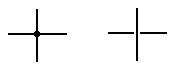 Before
we present our circuit, we introduce a notation used in
Before
we present our circuit, we introduce a notation used in
drawing two wires that appear to cross.
If a big dot is used at
the crossing, the two wires are connected.
If there is a gap, as in
the right figure, then the wires do not connect.
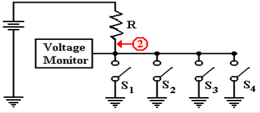
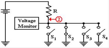
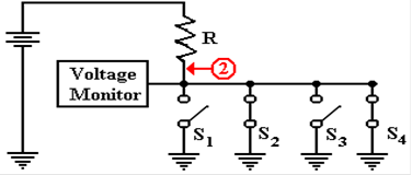
Here is a version of the circuit as we
shall use it later.
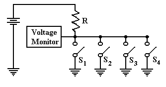
In this circuit, there are four switches
attached to the wire. The voltage is
monitored by
another circuit that is not important at this time. If all four switches are open, then the
voltage monitor registers full voltage.
If one or more of the switches is closed, the monitor
registers zero voltage. This is the best
way to monitor a set of switches.
Back
to Tri–State Buffers
We use the above verbiage to present a new view of tri–state buffers. Consider the following
two circuits, which have been used previously in this chapter. Suppose that the battery is
rated at five volts. In the circuit at
left, point A is at 5 volts and point B is at 0 volts. In the
circuit at right, point B is clearly at 0 volts, but the status of point A is
less clear.
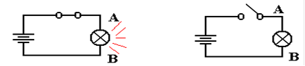
What is obvious about the circuit at
right is that there is no current flowing through it and no
power being emitted by the light bulb.
For this reason, we often say that point A is at 0 volts,
but it is better to say that there is no specified voltage at that point. This is equivalent to the
third state of a tri–state buffer; the open switch is not asserting anything at
point A.
Perhaps the major difference between the
two circuits is that we can add another battery to
the circuit at right and define a different voltage at point A. As long as the switch remains
open, we have no conflict. Were the
switch to be closed, we would have two circuits trying
to force a voltage at point A. This
could lead to a conflict.
Device
Polling
Here is a more common use of tri–state buffers. Suppose a number of devices, each of which
can signal a central voltage monitor by asserting logic zero (0 volts) on a
line. Recalling that
a logic AND outputs 0 if any of its inputs are 0, we could implement the
circuit as follows.
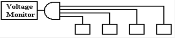
Suppose we wanted to add another
device. This would require pulling the
4–input AND gate
and replacing it with a 5–input AND gate.
Continual addition of devices would push the
technology beyond the number of inputs a normal gate will support.
The tri–state solution avoids these
problems. This circuit repeats the one
shown above with
the switches replaced by tri–state buffers, which should be viewed as switches.
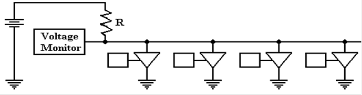
One should
note that additional devices can be added to this circuit merely by attaching
another tri–state switch. The only limit
to extensibility of this circuit arises from timing
considerations of signal propagation along the shared line.
Analysis of the Four–Tristate Circuit
In order to analyze the circuit
at the bottom of the previous page, we refer back to the circuit
on the page before that. We need to
understand the voltage at the monitor, which is assumed
to be the input to a digital gate in the control logic of the CPU. While a precise discussion of
this circuit involves treating resistors in parallel, such is not needed to be
accurate here.
First, assume
that none of the tri–states are enabled.
In that case, the circuit is equivalent to
the one in the next figure.
The voltage at
point 2 is the full
battery voltage, as the resistance
between that point and ground is
essentially infinite.
E2
= E / (1 + R1/R2)
E2 »
E ·
(1 – R1/R2),
but R1/R2 » 0.
Now consider
the situation in which one of the tri–state buffers is enabled. Tri–state 2 has
been chosen arbitrarily.
Now there is a
direct path of zero
resistance between point 2 and
ground. The voltage at that point
drops to 0, with the entire
voltage drop being across
the resistor R.
Finally
consider the situation in which more than one of the tri–state buffers is
enabled.
As before, the choice is arbitrary.
 Again,
there is a direct path of
Again,
there is a direct path of
zero resistance between point 2
and ground. The fact that there
are two such paths has no
practical consequences. The
only criterion is one or more
path of zero resistance.