Processing
Packed Decimal Data
The IBM System/360 is the
outgrowth of two earlier product lines: the 704/709/7090
series and the 702/705/7080 series.
The IBM 704/709/7090 series was
a line of computers designed to support scientific
research. This line supported binary
arithmetic. **
The IBM 702/705/7080 series was
designed to support commercial data processing.
This line supported packed decimal arithmetic.
The System/360 line was
designed to bring these two lines together and implement a
single architecture. For this reason, it
had to support both decimal and binary arithmetic.
** NOTE: The IBM 704 series had
a 36–bit instruction word in the following format.
|
3 bits |
15 bits |
3 bits |
15 bits |
|
Prefix |
Decrement |
Tag |
Address |
LISP was developed on a 704 in
1958. Think of the following:
CAR Contents of
the Address Part of the Register
CDR Contents of
the Decrement Part of the Register
Packed
Decimal Format
Arithmetic is done on data in
one of two formats: packed decimal or binary.
Here, we discuss the packed
decimal format, beginning with packed decimal constants.
A packed decimal constant is a
signed integer, with between 1 and 31 digits (inclusive).
The number of digits is always odd, with a 0 being prefixed to a constant of
even length.
A sign “half byte” or
hexadecimal digit is appended to the representation. The common
sign–representing hexadecimal digits are as follows:
C non–negative
D negative
F non–negative,
seen in the results of a PACK instruction.
If a DC (Define Constant)
declarative is used to initialize storage with a packed decimal
value, one may use the length attribute.
Possibly the only good use for this would be to
produce a right–adjusted value with a number of leading zeroes.
For example DC PL6’1234’ becomes
|
00 |
00 |
00 |
01 |
23 |
4C |
Remember that each of these
bytes holds two hexadecimal digits, not the value
indicated in decimal, so 23 is stored as 0010 0011 and 4C as 0100 1100.
Some
Examples and Cautions
Here are some standard uses.
DC P‘+370’ becomes 370C
DC P‘–500’ becomes 500D
DC P‘+92’ becomes 092C
Here are some uses that, while
completely logical, might best be avoided.
P1 DC
PL2‘12345678’ is truncated to become 678C.
Why give a value only to remove
most of it?
PCON DC
PL2‘123’,‘–456’,‘789’
This creates three constants, stored as 123C, 456D, and 789C.
Only the first constant
can be addressed directly.
I would prefer the following
sequence, with the labels P2 and P3 being optional.
P1 DC PL2‘123’
P2 DC PL2‘–456’
P3 DC
PL2‘789’
More
Examples
The
packed decimal format is normally considered as a fixed point format, with
a specified number of digits to the right of the decimal point.
It is
important to note that decimal points are ignored when declaring a packed
value.
When
such are found in a constant, they are treated by the assembler as comments.
Consider
the following examples and the assembly of each. Note that spaces have been
inserted between the bytes for readability only. They do not occur in the object code.
Statement Object Code Comments
P1 DC P‘1234’ 01
23 4C Standard expansion to 5 digits
P2 DC P‘12.34’ 01
23 4C The decimal is ignored.
P3 DC PL4‘-12.34’ 00 01 23 4D Negative and lengthened to 4
bytes. Leading zeroes added.
P4 DC PL5’12.34’ 00
00 01 23 4C Five bytes in length.
This gives
2
bytes of leading zeroes.
P5 DC 3PL2‘0’ 00
0C 00 0C 00 0C Three values, each 2 bytes.
Packed
Decimal: Moving Data
There
are two instructions that might be used to move packed decimal data from
one memory location to another.
MVC S1,S2 Copy characters from location S2 to
location S1
ZAP S1,S2 Copy the numeric value from location S2
to location S1.
Each of
the two instructions can lead to truncation if the length of the receiving
area,
S1, is less than the source memory area, S2.
If the
lengths of the receiving field and the sending field are equal, either
instruction
can be used and produce correct results.
The real
reason for preferring the ZAP instruction for moving packed decimal data
comes when the length of the receiving field is larger than that of the sending
field.
The ZAP
instruction copies the contents of the sending field right to left and
then pads the receiving field with zeroes, producing a correct result.
The MVC
instruction will copy extra bytes if the receiving field is longer than the
sending field. Whatever is copied is
likely not to be what is desired.
Bottom
line: Use the ZAP instruction to move
packed decimal data, and
be sure to avoid
truncation.
Packed Decimal
Data: ZAP, AP, CP, and SP
We have
three instructions with similar format.
ZAP S1,S2 Zero
S1 and add packed S2 (This is the move
discussed above)
AP S1,S2 Add
packed S2 to S1
CP S1,S2 Compare
S1 to S2, assuming the packed decimal format.
SP S1,S2 Subtract
packed S2 from S1.
These are of the form OP D1(L1,B1),D2(L2,B2), which provide
a 4–bit number representing the length for each of the two operands.
|
Type |
Bytes |
Form |
1 |
2 |
3 |
4 |
5 |
6 |
|
SS(2) |
6 |
D1(L1,B1),D2(L2,B2) |
OP |
L1 L2 |
B1 D1 |
D1D1 |
B2 D2 |
D2D2 |
The first byte contains the operation code, say X‘FA’ for AP or X‘F9’ for CP.
The second byte contains two hexadecimal digits, each representing an
operand length.
Each of L1 and L2 encodes one less than the length of
the associated operand. This
allows 4 bits to encode the numbers 1 through 16, and disallows arguments of 0
length.
The next four bytes contain two addresses in base register/displacement
format.
Packed Decimal
Data: Additional Considerations
For all
three instructions, the second operand must be a valid packed field terminated
with a valid sign. The usual values are
‘C’, ‘D’, and occasionally ‘F’.
For AP
and SP, the first operand must be a valid packed field terminated with a valid
sign. For ZAP, the only consideration is
that the destination field be large enough.
If
either the sending field or the destination field (AP and SP) have just been
created
by a PACK instruction, the sign half–byte may be represented by 0xF.
This is changed by the processing to 0xC or 0xD as necessary.
Some
textbook hint that using ZAP to transfer a packed decimal number with 0xF as
the sign half–byte will convert that to 0xC.
Any
packed decimal value with a sign half–byte of D (for negative) is considered to
sort less than any packed decimal value with a sign half–byte of C or F
(positive).
Example of
Packed Decimal Instructions
The form is OP
D1(L1,B1),D2(L2,B2). The object code format is as follows:
|
Type |
Bytes |
Form |
1 |
2 |
3 |
4 |
5 |
6 |
|
SS(2) |
6 |
D1(L1,B1),D2(L2,B2) |
OP |
L1 L2 |
B1 D1 |
D1D1 |
B2 D2 |
D2D2 |
Consider the assembly language statement below, which adds AMOUNT to TOTAL.
AP TOTAL,AMOUNT
Assume: 1. TOTAL is 4 bytes long, so it can hold at most 7 digits.
2. AMOUNT is 3 bytes long, so it can hold at most 5 digits.
3. The label TOTAL is at an address specified by a displacement
of X‘50A’ from the value
in register R3, used as a base register.
4. The label AMOUNT is at an address specified by a displacement
of X‘52C’ from the value
in register R3, used as a base register.
The object code looks like this: FA 32 35 0A 35 2C
Example of
Packed Decimal Instructions (Continued)
The form is OP
D1(L1,B1),D2(L2,B2). The object code format is as follows:
|
Type |
Bytes |
Form |
1 |
2 |
3 |
4 |
5 |
6 |
|
SS(2) |
6 |
D1(L1,B1),D2(L2,B2) |
OP |
L1 L2 |
B1 D1 |
D1D1 |
B2 D2 |
D2D2 |
Consider FA 32 35 0A 35 2C. The operation code X‘FA’ is that for the
Add Packed (Add Decimal) instruction, which is a type SS(2). The above format applies.
The field 32 is of the form L1 L2.
The
first value is X‘3’, or 3 decimal.
The first operand is 4 bytes long.
The
second value is X‘2’, or 2 decimal.
The second operand is 3 bytes long.
The two–byte field 35 0A indicates that register 3 is used as the base
register
for the first operand, which is at displacement X‘50A’.
The two–byte field 35 2C indicates that register 3 is used as the base
register
for the second operand, which is at displacement X‘52C’.
It is quite common for both operands to use the same base register.
Condition
Codes
Each of
the ZAP, AP, and SP instructions will set the condition codes. As a result,
one may execute conditional branches based on these operations. The branches are:
BZ Branch Zero BNZ Branch Not Zero
BM Branch if negative BNM Branch if
not negative
BP Brach if positive BNP Branch
if not positive
BO Branch on overflow BNO Branch if
overflow has not occurred.
An overflow will occur if the receiving
field is not large enough to accept the result.
My guess
is that leading zeroes are not considered in this; so that the seven digit
packed
decimal number 0000123 can be moved to a field accepting four digit packed
numbers.
Comparing
Packed Decimal Values
The CP (Compare Packed) instruction is used
to compare packed decimal values.
This
sets the condition codes that can be used in a conditional branch instruction,
as just
discussed. Is there any reason to
compare and not then have a conditional branch?
In some
sense, the CLC (Compare Character)
instruction is similar and may be used
to compare packed decimal data. However,
this use is dangerous, as the CLC does not
allow for many of the standards of standard algebra.
Consider
the two values 123C (representing +123) and 123D (representing –123).
CP will correctly state that 123D <
123C; indeed –123 is less than +123.
CLC will state that 123D > 123C, as
12 = 12, but 3D > 3C. Remember that
these are being compared as
sequences of characters without numeric values.
Consider
the two values 123C (representing +123) and 123F (also representing +123).
CP will correctly state that 123C =
123F; as 123 = 123.
CLC will state that 123F > 123C, as
12 = 12, but 3F > 3C.
Consider
the two values 125C (representing +123) and 12345C (representing +12345).
CP will work correctly, noting that
12345 > 00125. CLC will compare
character by character. As ‘5’ > ‘3’, it will conclude that 125
> 12345.
PACK
We now focus on conversions of
decimal data between the two formats that may
be used to represent them:
1. The EBCDIC
character encoding used for input and output.
2. The packed
decimal format used for decimal arithmetic.
The PACK instruction can be
used to convert data from zoned format into the packed
decimal format. For the moment, we shall
not cover zoned decimal format.
The standard discussion of the
PACK instruction focuses on positive numbers.
Consider the input data string
“9876”.
Represented in EBCDIC, the
string would be F9 F8 F7 F6.
One would expect this to pack
to the three byte value 09 87 6C.
In fact, it packs to a variant
of positive format 09 87 6F.
This value will be converted to the more standard representation when
it is first used by a packed decimal instruction.
NOTE: What about the input sequence
“–123”, which is represented by the
EBCDIC string
60F1F2F3. It should pack to 123D, but it
does not.
The PACK instruction is
not designed to handle a leading “–”
Packing
Blanks
A serious problem can arise if
the field to be packed contains all blanks
(EBCDIC code 0x40).
Consider the five character
input “ ” or EBCDIC 40 40 40 40 40.
This will pack to the string “000004”, which lacks a valid sign.
This invalid packed input
cannot be processed by any packed decimal instruction.
Some authors suggest checking
all input fields and replacing those that are blank
with all zeroes. This suggests a very
common meaning of blanks as equivalent to 0.
Here is the code, directly from
Abel’s textbook. The input field, RATEIN, is
supposed to contain one to five digits, but no more than five.
CLC RATEIN,=CL5‘ ’ Is this a field of five blanks
BNE D50 No,
it is not all blanks
MVC RATEIN,=CL5‘00000’ Replace 5 blanks with 5 zeroes
D50 PACK
RATEPK,RATEIN Store packed value in RATEPK
More on
Input of Packed Data
Recall that the input of packed
data is a two–step procedure.
1. Input the digits
as a string of EBCDIC characters.
2. Convert the
digits to packed format.
The format of the input is
dictated by the appropriate data declarations.
In this example, we consider
the following declaration of the form
of the input, which is best viewed as an 80–column card.
RECORDIN DS
0CL80 80 CHARACTER CARD IMAGE
DIGITS DS
CL5 FIRST FIVE COLUMNS ARE
INPUT
FILLER DS
CL75 THE OTHER 75 ARE IGNORED
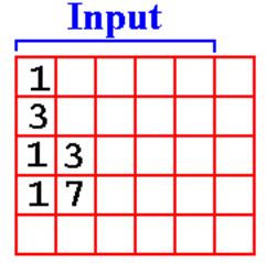
Here is a properly
formatted input sequence.
1 Four blanks before the “1”.
3
13 Three blanks before the
“13”.
Another Look
at This Input
The important part of the data
declaration for the input is as follows.
RECORDIN DS
0CL80 80 CHARACTER CARD IMAGE
DIGITS DS
CL5 FIRST FIVE COLUMNS ARE
INPUT
Here is the properly
formatted input, viewed in columns.
Reading from right to left: Column 5 is the units column
Column
4 is the tens column
Column
3 is the hundreds column, etc.
Note
that each digit is properly placed; the first line is really 00001.
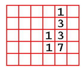
One Error:
Assuming Free–Formatted Input
Here
is some input from the same program. It did not work.
1
3
13
17
Here is the way that the
input was interpreted.
To
me this looks like 10000 + 30000 + 13000 + 17000.
The Output
for the Erroneous Input
I
had expected the above input to give a sum of 70000. It did not.
Here
is the actual output. All we get is the
print echo of the first line input.
***PROGRAM FOUR CSU SPRING 2009
***********
1
Here
is the code loop for the processing routine.
B10DOIT MVC DATAPR,RECORDIN FILL THE PRINT AREA
PUT PRINTER,PRINT START THE PRINT
PACK
PACKIN,DIGITSIN CONVERT INPUT TO DECIMAL
AP
PACKSUM,PACKIN ADD IT
UP
BR
R8 RETURN FROM SUBROUTINE
What
is the problem. Each of the first two
lines worked.
It
is either the PACK or the AP instruction that fails.
A Diagnostic
Here
is the code that isolated the problem.
Note the one line commented out.
B10DOIT MVC DATAPR,RECORDIN FILL THE PRINT AREA
PUT PRINTER,PRINT START THE PRINT
PACK PACKIN,DIGITSIN CONVERT
INPUT TO DECIMAL
*** AP PACKSUM,PACKIN ADD IT UP
BR
R8 RETURN FROM SUBROUTINE
Here
is the output for the code fragment above.
**************
TOP OF DATA *****************************
***PROGRAM FOUR CSU SPRING 2009
***********
1
3
13
17
THE SUM =
000000
************
BOTTOM OF DATA ****************************
The
Diagnosis
Look
again at the input.

The
first line, as EBCDIC characters is read as follows.
F1 40 40 40 40
The
PACK command processes right to left. It
will process any kind of data,
even data that do not make sense as digits.
The
above will pack to something like X‘10004’, an invalid packed format.
With
no valid sign indicator, the AP instruction will fail.
Printing
Packed Data
In
order to print packed decimal data, it must be converted back to a string
of EBCDIC characters.
The
unpack command, UNPK, appears to convert data in Packed Decimal
format to EBCDIC format, actually converts to Zoned Decimal format.
UNPK
almost converts to EBCDIC. It has an unfortunate
side effect, due to the
simplicity of its implementation, which is a direct conversion to Zoned format.
The
problem occurs when handling the sign code, “C” or “D” in the Packed
Decimal format. This occurs in the
rightmost byte of a packed decimal value.
Consider
the decimal number 47, represented in binary in register R4.
CVD
R4,PACKOUT produces the packed decimal 047C. This is
correct.
When
this is unpacked it should become F0 F4 F7
Unpack
just swaps the sign half byte: F0 F4 C7.
This
prints as 04G, because 0xC7 is the EBCDIC code
for the letter ‘G’.
We have to correct the zone
part of the last byte.
Printing
Packed Data (Part 2)
Here
is the code that works for five digit numbers.
It is written as a
subroutine, that is called as BALR R8,NUMOUT.
NUMOUT CP
QTYPACK, =P‘0’
BNM
NOTNEG
MVI
QTYOUT+5,C‘-’ PLACE SIGN AT
QTYOUT+5
NOTNEG UNPK QTYOUT,QTYPACK PRODUCE FORMATTED NUMBER
MVZ QTYOUT+4(1),=X’F0’ MOVE 1 BYTE
* TO ADDRESS QTYOUT+4
BR 8
RETURN ADDRESS IN REGISTER
8
QTYPACK DS PL3
HOLDS FIVE DIGITS IN THREE
BYTES
QTYOUT DS 0CL6
DIGITS DS
CL5 THE FIVE DIGITS
DC CL1’ ’ THE SIGN
Again, the expression QTYOUT+4 is an address, not a value.
If QTYOUT holds C‘01234’, then QTYOUT+4 holds C ‘4’.
Unpacking
and Editing Packed Decimal Data
Each of the UNPK (Unpack) and
the ED (Edit) instruction will convert packed
decimal data into a form suitable for printing.
The ED instruction seems to be
the more useful. In addition to
producing the
correct print representation of all digits, it allows for the standard output
formats.
The use of the ED
instruction is a two–step process.
1. Define an edit
pattern to represent the punctuation, sign, and handling of
leading zeroes that is
required. Use the MVC instruction to
move
this into the output
position.
2. Use the ED
instruction to overwrite the output position ** with the output
string that will be
formatted as specified by the edit pattern.
Here is an example. Note that there are a number of length
constraints, specifically
that the length of the edit pattern match the length of the output area.
** NOTE: The first character in the edit pattern is a fill character.
It is not
overwritten.
ED
Instruction: A Simple Example
Here is the book’s example
MVC COUNPR,=X‘40202020’ Four bytes of pattern
ED COUNPR,COUNT
More code here
COUNPR
DS CL4
Note the
sequence of events in these two lines of code.
1. The
edit pattern is moved into the output field.
The leading pair of hexadecimal
digits, 0x40, state that a
blank,‘ ’, will replace all leading zeroes.
2. The
decimal value is edited into the output field COUNPR, overwriting
the edit pattern.
The
result is printed as the four character sequence “ 1”,
represented in EBCDC
code as 0x404040F1.
ED: Basic
Rules
The
basic form of the instruction is ED S1,S2
The first
operand, S1, references the leftmost byte of the edit word, which
has been placed in the output area.
The
second operand, S2, references a packed field to be edited.
One key
concept in the editing for output is called “significance”. In many
uses,
leading zeroes are not treated as significant and are replaced by the fill
character.
Thus,
the number 001 would print as “1”.
There
are times in which one wants one or more leading zeroes to be printed. As an
example, consider the real number 0.25, which is stored as 025C. It might best be
printed as “0.25” with at least one leading zero. This leads to the concept called
“forcing significance”, in which
leading zeroes are printed.
The Fill
Character
The
leftmost hexadecimal byte in the output area before the execution of the
instruction begins represents the fill character to use when replacing
non–significant
leading zeroes. Two standard values are:
0x40 a
blank ‘ ’
0x5C an
asterisk ‘*’ Often used in check printing.
Consider
the three digit number 172, stored internally as 172C. For now,
assume that
the field from which it will be printed allows for five digits.
With a
fill character of 0x40 (blank), this would normally be printed as 172.
We force
significance to cause either 0172 or 00172 to be printed.
For this number,
with a fill character of 0x40, our options would be one of the three following.
172
0172
00172
With a
fill character of 0x5C, we might have one of the three following.
**172
*0172
00172
The Edit
Word: Encountering Significance
Here are
some of the commonly used edit characters.
Note that it is more convenient
to represent these by their hexadecimal EBCDIC.
One key
idea is the encounter of significance. The instruction generates digits for
possible printing from left (most significant) to right (least
significant). Two events
cause this encounter: 1) a non–zero digit is generated, and 2) a digit is
encountered
that is associated with the 0x21 edit pattern.
As noted
above, the first character is the fill character. The other codes are
0x20 Digit
selector. This represents a digit to be
printed, unless it
happens to
be a leading non–significant zero.
In that
case, the fill character is printed.
0x21 Digit
selector and significance starter. This
not only represents a
digit to
be printed, but it also forces significance.
Each digit
to the
right will be printed, even if a leading zero.
Note: Unless one is careful, ED might result in an
output field that is all blanks.
For printing integer values, one might seriously
consider ending the edit pattern (word)
with the values 0x2120. Significance
is forced after the next–to–last digit, forcing at
least one digit to be printed.
The Edit
Word: Formatting the Output
Part of
the function of the ED command is to allow standard formatting of the
output,
including decimal points and commas.
Handling of negative numbers is a bit strange.
Here are
the standard formatting patterns.
0x4B The
decimal point. If significance has been
encountered, the decimal
point is
printed. Otherwise, the fill character
is printed.
0x6B The
comma. If significance has been
encountered, the comma is
printed. Otherwise, the fill character is printed.
0x60 The
minus sign, “–”. This is used in an
unexpected way.
The
standard for use of the minus sign arises from conventions found in commercial
use. The minus sign is placed at the end of the number.
Thus the
three digit positive number 172 would be printed as 172
and the three digit negative number –172 would be printed as 172–.
The edit
pattern for this output (ignoring the significance issue) would be as follows:
0x4020202060. The
fill character is a blank. There are
three digits followed by
a
sign field, which is printed as either “–” or the fill character.
ED: An
Example with Formatting
In this
example, it is desired to print a seven digit number, formatted as follows.
1. It
is a fixed point number, with two digits to the right of the decimal.
2. It
has five digits to the left of the decimal and places a comma in the
standard location if
significance has been encountered.
3. It
will be printed with a terminating “–” if the number is negative.
This
situation is illustrated in the following graphic.
The edit
pattern for this example would be as follows:
|
|
1 |
2 |
|
3 |
4 |
5 |
|
6 |
7 |
|
|
40 |
20 |
20 |
6B |
20 |
21 |
20 |
4B |
20 |
20 |
60 |
Note: The significance forcer at digit 4 will insure
that digit 5 is printed,
even if it is a zero.
ED: Why the
“*” Fill Character
One
option for the fill character is 0x5C, the asterisk.
Why is this used?
Consider
the above seven–digit example, in which the number is to be viewed
as a money amount. We shall use the
dollar sign, “$”, in the amount.
Consider
the amount $123.45. We would like
to print it in this fashion,
but placing the dollar sign in this way presents difficulties.
Standard
coding practice would have been to place the dollar sign in a column
just prior to that for the digits. The
format would have been as follows.
|
Column |
0 |
1 |
2 |
3 |
4 |
5 |
6 |
7 |
8 |
9 |
10 |
|
|
$ |
Digits |
, |
Digits |
. |
Digits |
– |
||||
If
the blank fill character were chosen, this would print as $ 123.45.
Note the spaces before the first digit.
To prevent fraud, we print $***123.45
ED: A More
Complete Example
We
now show the complete code for producing a printable output from the
seven digit packed number considered above.
We shall use “*” as a fill character.
Note
that the output will be eleven EBCDIC characters.
Here is
the code.
PRINTAMT MVC AMNTPR,EDITWD
ED
AMTPR,AMTPACK
*
EDITWD DC X‘5C20206B2021204B202060’
*
AMTPACK DS PL4
FOUR BYTES TO STORE SEVEN DIGITS.
*
AMTOUT DS 0CL12
TWELVE EBCDIC CHARACTERS
DOLLAR DC C‘$’
THE DOLLAR SIGN
AMTPR DS CL11
THE FORMATTED PRINT OUTPUT
ED: Another Example Using an Edit Pattern
This
example is adapted from the textbook.
Suppose that we have the following.
The
packed value to be printed is represented by
DC PL3‘7’ This is
represented as 00 00 7C.
The edit
pattern, when placed in the output area beginning at byte address 90,
is as shown below.
|
Address |
90 |
91 |
92 |
93 |
94 |
95 |
96 |
97 |
|
Code |
40 |
20 |
21 |
20 |
4B |
20 |
20 |
60 |
Note
the structure here: 3 digits to the left
of the decimal (at least one will be printed),
the
decimal point, and
two
digits to the right of the decimal.
This
might lead one to expect something like “000.07” to be printed.
We now
follow the discussion on pages 181 and 182 of the textbook and note a
discrepancy in the books description. We
shall see what to make of this.
ED: First Two Digits
At
address 90 the contents are 0x40,
assumed to be the fill character.
This
location is not altered.
|
Address |
90 |
91 |
92 |
93 |
94 |
95 |
96 |
97 |
|
Code |
40 |
20 |
21 |
20 |
4B |
20 |
20 |
60 |
At
address 91 the contents 0x20 is a
digit selector. The first digit
of the
packed amount is examined. It is a 0. 00007C
ED
replaces the 0x20 with the fill character, 0x40.
|
Address |
90 |
91 |
92 |
93 |
94 |
95 |
96 |
97 |
|
Code |
40 |
40 |
21 |
20 |
4B |
20 |
20 |
60 |
At
address 92 the contents 0x21 is a
digit selector and a significance forcer
for what
follows. The second digit 00007C
of the
packed amount is of the packed amount is examined.
It is a
0. ED replaces the 0x21 with the fill
character, 0x40.
|
Address |
90 |
91 |
92 |
93 |
94 |
95 |
96 |
97 |
|
Code |
40 |
40 |
40 |
20 |
4B |
20 |
20 |
60 |
ED: Next Two Digits
At
address 93 the contents 0x20 is a
digit selector. Significance has been
encountered. The third digit of the packed 00007C
amount is
of the packed amount is examined.
It is a
0. ED replaces the 0x20 with 0xF0, the
code for ‘0’.
|
Address |
90 |
91 |
92 |
93 |
94 |
95 |
96 |
97 |
|
Code |
40 |
40 |
40 |
F0 |
4B |
20 |
20 |
60 |
At address 94 the contents 0x4B indicate that a
decimal point is to be printed
if
significance has been encountered. It
has been, so the pattern
is not
changed. Had significance not been
encountered, this
would have
been replaced by the fill character.
|
Address |
90 |
91 |
92 |
93 |
94 |
95 |
96 |
97 |
|
Code |
40 |
40 |
40 |
F0 |
4B |
20 |
20 |
60 |
At
address 95 the contents 0x20 is a
digit selector. Significance has been
encountered. The fourth digit of the packed 00007C
amount is of
the packed amount is examined.
It is a
0. ED replaces the 0x20 with 0xF0, the
code for ‘0’.
|
Address |
90 |
91 |
92 |
93 |
94 |
95 |
96 |
97 |
|
Code |
40 |
40 |
40 |
F0 |
4B |
F0 |
20 |
60 |
ED: Last Digit
At
address 96 the contents 0x20 is a
digit selector. Significance has been
encountered. The fourth digit of the packed 00007C
amount is
of the packed amount is examined.
It is a
7. ED replaces the 0x20 with 0xF7, the
code for ‘7’.
|
Address |
90 |
91 |
92 |
93 |
94 |
95 |
96 |
97 |
|
Code |
40 |
40 |
40 |
F0 |
4B |
F0 |
F7 |
60 |
At address 97 the contents 0x60 indicate to place a
minus sign if the number
to be
printed is found to be negative. It is
not, so the instruction
replaces
the negative sign with the fill character.
|
Address |
90 |
91 |
92 |
93 |
94 |
95 |
96 |
97 |
|
Code |
40 |
40 |
40 |
F0 |
4B |
F0 |
F7 |
40 |
At this point, the
process terminates. We have the EBCDIC
representation of
the string to be printed. As characters,
this would be “ 0.07 ”.
Note that additional
code would be required to print something like “ $ 0.07 ”.
This would involve a scan of the output of the ED instruction and placing the
dollar
sign at a place deemed appropriate.