Consider what happens in
Overwrite Mode. First position the
cursor after the BBB to get
AAABBB|CCC
Then backspace three times to
get the string
AAA|CCC
Then enter the string “DDD”. The result is logical, but surprising. The new string is
AAADDD|
What has happened is that the “CCC” in the string “AAACCC” has been overwritten to produce the result “AAADDD”. The “CCC” was not “moved over” so that the string “DDD” could be placed in front of it; the string “CCC” just replaced the next three characters in the old string.
Be Cautious About “Non Standard” Keys
Here I have a very precise definition for the non–standard term “Non Standard Key”. It is a key that does not immediately correspond to a key on the IBM 029 card punch. Within this arbitrary definition, let us stipulate that lower case letters correspond to upper case letters, all of which are present on the IBM 029.
With a few exceptions, the “standard keys” are those that produce printable characters. One way to refer to this set of keys is to call them the “Character Keys”, though this is not a standard usage. On the standard keyboard, these include the alphabetical keys, the digit keys directly above them, the space bar (it produces the “ ” character), the shift key (which produces no character), and the characters generated by pressing the shift key and one of the other mentioned keys. This set of keys specifically DOES NOT INCLUDE the keys in the Numeric Keypad to the right of a standard keyboard.
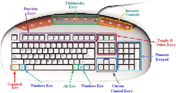
We now note that most terminal emulators are not guaranteed to handle all of the standard keys correctly. Let us ignore the Multimedia Keys and Internet Controls (which nobody would expect to work) and discuss the other keys.
The Numeric Keypad keys emit scan codes that may differ from those emitted by the digit keys that are at the top of the alphabetical set. These might be converted into different EBCDID codes by the terminal emulator, and thus be misinterpreted by the Mainframe.
The Toggle Keys emit codes that generally have no meaning to most terminal emulators.
The Cursor Control Keys can be used in certain contexts, such as moving over text. They should not be viewed as introducing a space character, though they may seem to do so.
The Function Keys are correctly interpreted by the emulator and passed to the Mainframe.
The following keys can be used with the standard terminal emulator packages: the character keys, the Function Keys, and (occasionally) the Cursor Control Keys. In general, the Control Key, Alt Key, Windows Key, keys in the Numeric Keypad, and the Toggle Keys should be avoided. While these often work, they occasionally will cause the keyboard to freeze.
Logging onto the Mainframe
The first step is to run a
terminal emulator. What we have on the
computers
at CSU is called “zScope Classic”, currently version 5.1. I double click the icon.
The program starts. In the status line at the bottom of the screen and below what will become the display, one sees two words: “OFF LINE” and “Overwrite”. The standard for the mainframe is editing in the overwrite mode, in which the characters typed will replace the existing characters. The “OFF LINE” is an indication that one needs to connect to the mainframe before proceeding.
Go to the File menu at the top and click on Connect (Alt C). Another option is to click on the “lightning bolt” icon just below the File menu. You will be connected to the mainframe. At this point, you should see a splash screen with “ENTER L FOLLOWED BY THE APPLID YOU WISH TO LOGON TO”. Immediately we see that we have landed in UPPERCASE LAND, the standard style for the classis mainframe application. You might as well set the “CAPS LOCK” on your keyboard.
L TSO
Enter the above line, followed by a carriage return (the Enter key). You will be prompted for a user ID. I entered my seven–character ID. You should use the user ID assigned to you by the instructor. You are taken to another screen, with the cursor positioned at the place for entry of your seven–character password.
If this is your first use of the mainframe, your password will
be set to your user ID. You will be
required to change the password before proceeding. Enter the password followed by a CR (hit the
enter key). DO NOT USE MORE THAN SEVEN CHARACTERS FOR THE PASSWORD,
as this can lead to effects that will appear to be random, though they are
predictable.
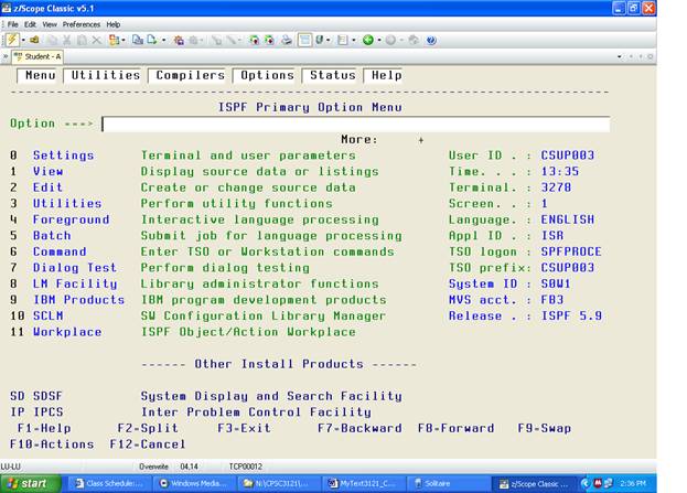
At this point, you will see several screens of announcements, the last one ending with “LAST MESSAGE FROM VENDOR.CLIST”. Hit the Enter Key at the end of each of these displays. On hitting the Enter Key after the last key, you will be presented with the ISPF Primary Options Menu (shown below, using my display option).
If you use another screen style, your display will appear different, but have this content.
Editing a File
There are two tasks here: find the file that you want to edit and actually editing it.
I chose menu option 2. This takes me to a menu with a lot on it, including:
ISPF Library
Project _________
Group _________
Type _________
Member _________
For the project enter your user ID. This is an assembly language course, so the
group is ASM.
We edit source code, so the Type is SRC.
Since I have logged on before, the system remembers what I last looked
at and displays as follows.
ISPF Library
Project CSU0003__
Group ASM______
Type SRC_____
Member _________
This is what I want, so I hit the enter key.
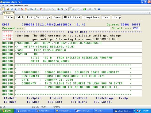
The EDIT Screen
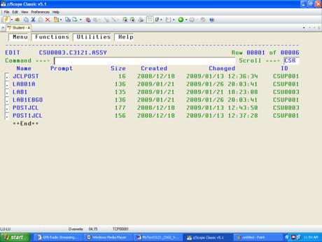
What now displays is titled “EDIT CSU0003.CS3121.ASSY”. I would call it a “File Listing”, though I am confident that this is not IBM terminology. I now must select a file to edit.
My listing shows five lines, appearing approximately as follows.
JCLPOST
LAB1
LAB1EBGO
POSTJCL
POST1JCL
It is time to select a line and thereby select a file to be edited. It is here that we first encounter what I call “dual mode” editing. At times certain keys act as commands to the system, moving the cursor and so forth. At other times, the keys act as text to be input into a file.
Here use the TAB key as a command key to move the cursor to
the dot in front of the name
of the file that you want to edit. I
have chosen LAB1EBGO. Input the single
character “S”, followed by the ENTER key to edit the file. You are in Command Mode.
You should now see a screen that resembles the following. We shall discuss this later.
A Sample Program
Here is the complete text of the
sample program, listed with the line numbers removed.
There are two reasons for this: 1.
The student will not type in any line number, and
2,
With line numbers, I could not fit this on the page.
This listing is “as is”; later we shall comments on the program section by section.
//CSU0003A
JOB (ASSY),'ED BOZ',CLASS=A,MSGCLASS=A,
// NOTIFY=&SYSUID,MSGLEVEL=(0,0)
//ASM EXEC PROC=HLASMCLG
//SYSIN DD
*
TITLE
'ED B - FROM SKELETON ASSEMBLER PROGRAM'
PRINT
ON,NODATA,NOGEN
******************************************************************
*
*
* PROGRAMMER:
EDWARD BOSWORTH,
* ASSIGNMENT:
FIRST LAB ASSIGNMENT FOR CPSC 3121 *
* DATE
: JANUARY 21, 2009 *
* COMMENTS
: THIS ALLOWS THE STUDENT TO LEAN
HOW TO ENTER *
* :
A PROGRAM ON THE MAINFRAME AND EXECUTE IT. *
*
*
******************************************************************
*
*
* REGISTER EQUATES
*
* *
******************************************************************
R0 EQU
0
R1 EQU
1
R2 EQU
2
R3 EQU
3
R4 EQU
4
R5 EQU
5
R6 EQU
6
R7 EQU
7
R8 EQU
8
R9 EQU
9
R10 EQU
10
R11 EQU
11
R12 EQU
12
R13 EQU
13
R14 EQU
14
R15 EQU
15
******************************************************************
LAB1 CSECT
SAVE
(14,12) SAVE THE
CALLER'S REGISTERS
BALR
R12,0 ESTABLISH
USING *,R12 ADDRESSABILITY
LA
R2,SAVEAREA ADDRESS OF
MY SAVE AREA
ST
R2,8(,R13) FORWARD
CHAIN MINE
ST
R13,SAVEAREA+4 BACKWARD
CHAIN CALLER'S
LR
R13,R2 SET 13
FROM MY SUB CALLS
***************************************************
*
BEGIN THE PROGRAM LOGIC. FIRST OPEN THE INPUT AND OUTPUT
*
OPEN
(PRINTER,(OUTPUT))
OPEN
(FILEIN,(INPUT))
PUT
PRINTER,PRHEAD PRINT THE
HEADER
GET
FILEIN,RECORDIN GET THE
FIRST RECORD, IF THERE
*
* READ AND PRINT
*
A10LOOP MVC
DATAPR,RECORDIN MOVE INPUT
RECORD
PUT
PRINTER,PRINT PRINT THE
RECORD
GET
FILEIN,RECORDIN GET THE
NEXT RECORD
B
A10LOOP GO BACK
AND PROCESS
*
* END OF INPUT PROCESSING
*
A90END CLOSE (FILEIN) CLOSE THE FILES...
CLOSE (PRINTER)
L
R13,SAVEAREA+4 POINT AT
OLD SAVE AREA
LM
R14,R12,12(R13) RESTORE
THE REGISTERS
LA
R15,0 RETURN
CODE = 0
BR
R14 RETURN TO OPERATING SYSTEM
******************************************************************
*
*
* OUTPUT FILE - DATA CONTROL BLOCK *
*
*
******************************************************************
PRINTER DCB DSORG=PS,
X
MACRF=(PM), X
DEVD=DA,
X
DDNAME=PRINTER, X
RECFM=FM,
X
LRECL=133
******************************************************************
*
*
* INPUT FILE - DATA CONTROL BLOCK *
*
*
******************************************************************
FILEIN DCB DSORG=PS,
X
MACRF=(GM), X
DEVD=DA,
X
DDNAME=FILEIN, X
EODAD=A90END, X
RECFM=FB,
X
LRECL=80
******************************************************************
*
* INPUT RECORD AREA
*
******************************************************************
RECORDIN
DS CL80
******************************************************************
*
* OUTPUT RECORD AREA
*
******************************************************************
*
* HERE IS THE HEADER FOR SPRING 2009
*
PRHEAD
DS 0CL133
PRC1 DC
C' ' PRINT CONTROL -
PRINT ON NEXT LINE
DC
CL10' '
DC
CL122'***COLUMBUS STATE UNIVERSITY SPRING 2009***'
*
PRINT DS
0CL133 PRINT
AREA
PRC2 DC
C' ' PRINT CONTROL
CHARACTER
DC
CL10' '
DATAPR
DC CL80' '
DC
CL42' '
******************************************************************
*
* REGISTER SAVE AREA
*
******************************************************************
SAVEAREA
DS 18F
******************************************************************
*
* LITERAL POOL - THIS PROGRAM DOES NOT USE
LITERALS.
*
******************************************************************
* LTORG *
END
LAB1
/*
//G.PRINTER
DD SYSOUT=*
//G.FILEIN DD *
LINE
1 SPRING 2009
LINE
2 SPRING 2009
LINE
3 SPRING 2009
LINE
4 SPRING 2009
/*
//
Column Conventions in the Assembler Program
The column conventions are as follows:
Columns 1 – 8 The name or label of the statement or declarative
Column 9 This must be blank
Columns 10 – 14 The operation: instruction, declarative, or macro
Column 15 This must be blank
Columns 16 –
71 The operands for the operation.
Any
continuation line must begin in column 16.
Column 72 If nonblank, the next line is a continuation of this one.
Consider the following example, taken from the sample program.
PRINTER
DCB DDNAME=PRINTER, X
DSORG=PS,
X
DEVD=DA,
X
MACRF=(PM), X
LRECL=133, X
RECFM=FM
The label PRINTER is placed in columns 1 – 7
The DCB macro is placed in columns 10 – 12
The arguments are placed in columns 16 – 71, the continuation mark is in column 72.
More on Column Conventions
Were we to use the COLS command
in the editor, we would see the following
for the first line of the statement above.
PRINTER DCB DDNAME=PRINTER, X
000000000111111111122222222223333333333444444444455555555556666666666777
123456789012345678901234567890123456789012345678901234567890123456789012
Coding forms
It used to be common practice
to have coding forms with the columns clearly indicated.
On such a form, the DCB statement might appear as follows, except that the form
would have been used by a human; thus the text would have been hand written.
We shall discuss the meaning (semantics) of this statement in
a later slide.
At the moment, the only point is to emphasize the importance of proper column
alignment.
The Sample Program with
Comments
These notes will focus on a sample program that was assigned for all students to execute on the mainframe. This lecture contains both code fragments and annotations on those code fragments. Code fragments will be presented in the font Courier New (bold), as follows.
SAVE
(14,12)
All other material will be in the standard font Times New Roman, as is this sentence.
The student will recall that the input to the assembler is not free–form; column placement is extremely important. Your instructor discovered this fact when an otherwise correct program would not assembly correctly.
We first list the entire program, as it would appear in the IBM editor before being submitted for execution. We then present a series of comments on the sample program.
Job Control Statements
In order to understand the structure of the sample program, one must imagine a “batch job”, which is a sequence of cards submitted to the computer.
Your input file comprises a sequence of lines of text. Each line of text should be
viewed as a “card image”, basically eighty characters with some of them blanks.
Here is the job control language from my submission of the program.
//CSU0003A JOB (ASSY),'ED
BOZ',CLASS=A,MSGCLASS=A,
//
NOTIFY=&SYSUID,MSGLEVEL=(0,0)
//ASM
EXEC PROC=HLASMCLG
//SYSIN
DD *
Each student should employ a unique job name based on the user
ID (mine is obviously CSU0003), with a single letter appended. The notify line should contains the string
“&SYSUID”, indicating that the user should receive all notifications.
The next line seems to indicate to execute HLASM, the high level assembler, with the option to compile, load, and go – assemble the program and execute it.
The next line indicates that the input will be from the lines of text following the JCL.
The next line invokes the TITLE macro to place the title at the top of each printed page.
TITLE 'ED B - FROM SKELETON
ASSEMBLER PROGRAM'
PRINT ON,NODATA,NOGEN
The assembler directive PRINT
ON,NODATA,NOGEN deserves a comment.
This is a directive to the assembler on formatting the listing, but not
to expand the macros (defined later).
The course will include an assignment in which you will write your own
macros. When you do that, change the
above print directive to
PRINT
ON,NODATA,GEN so that you can see your macro expansions.
The next section of the code shows some comments. Within the context of the assembler program, any line of text that begins with an asterisk (“*”), is taken as a comment.
****************************************************************
*
*
PROGRAMMER: EDWARD BOSWORTH,
*
ASSIGNMENT: FIRST LAB ASSIGNMENT
FOR CPSC 3121
*
DATE : JANUARY 21, 2009
*
COMMENTS : THIS ALLOWS THE STUDENT TO LEAN HOW TO
ENTER
*
: A PROGRAM ON THE MAINFRAME AND
EXECUTE IT.
*
****************************************************************
The Register Equates
The next section of the code contains a number of EQU statements. This is essentially a set of substitution statements allowing use of labels for the numeric register designators. Without these, one would have to write code such as BALR 12,0 rather than BALR R12,0.
****************************************************************
*
REGISTER EQUATES
****************************************************************
R0
EQU 0
R1
EQU 1
R2
EQU 2
R3
EQU 3
R4
EQU 4
R5
EQU 5
R6
EQU 6
R7
EQU 7
R8 EQU
8
R9
EQU 9
R10
EQU 10
R11
EQU 11
R12
EQU 12
R13
EQU 13
R14
EQU 14
R15
EQU 15
**************************************************************
The next section of code should be viewed as the start of the executable part of the program. The structure of this part reflects the reality that a user program is handled by the Mainframe Operating System as a subroutine or function. What this section of code does is to set up the standard linkage from a subprogram to the program that called it. This is useful for processing error output, and allows operations such as tracing the call stack, etc.
Here is the code section.
**************************************************************
LAB1
CSECT
SAVE
(14,12) SAVE THE CALLER'S REGISTERS
BALR R12,0 ESTABLISH
USING *,R12
ADDRESSABILITY
LA R2,SAVEAREA ADDRESS OF MY SAVE AREA
ST R2,8(,R13) FORWARD CHAIN MINE
ST R13,SAVEAREA+4 BACKWARD CHAIN CALLER'S
LR R13,R2 SET 13 FROM MY SUB CALLS
**************************************************************
This code should be viewed as “boilerplate”, which is code that should be the start of any program written. All assembler language programs should start this way, changing only the label before the “CSECT”, which should be viewed as the name of the program.
The first line LAB1 CSECT is a declaration of a Control Section, named “LAB1”.
By definition, a control section is “a block of coding that can be relocated (independent of other coding) without altering the operating logic of the program”. Practically, a control section is just one block of assembly code that can be assembled and executed independently.
Opening the Input and Output
As indicated, the next section of code opens the input and output and prints a header line to the output. Unlike the book’s example, this does not skip to a new page.
* SET UP THE
INPUT AND OUTPUT AND PRINT HEADERS
*
OPEN
(PRINTER,(OUTPUT)) OPEN THE STANDARD
OUTPUT
OPEN
(FILEIN,(INPUT)) OPEN THE STANDARD
INPUT
PUT
PRINTER,PRHEAD PRINT HEADER
GET
FILEIN,RECORDIN GET THE FIRST
RECORD, IF THERE
*
This example uses the macros associated with the IBM OS operating system. Note that the input and output can be opened in any order, provided that each is opened before its first use.
Note that the open of the input and the output can be combined into a single statement.
OPEN
(FILEIN,(INPUT), PRINTER,(OUTPUT))
Your instructor prefers to use separate statements, one for
each I/O file.
This should be viewed as a personal preference only.
When the input FILEIN is defined, the declaration includes a specification of the line of code to be executed when an End–of–File exception is raised. We shall say more on this later. At present, the program prints a header and attempts to get a line of input.
The Print
Here is the “main body” of the assembly code.
GET
FILEIN,RECORDIN GET THE FIRST
RECORD
* IF IT IS THERE
* READ AND
PRINT
*
A10LOOP MVC
DATAPR,RECORDIN MOVE INPUT
RECORD
PUT
PRINTER,PRINT PRINT THE
RECORD
GET
FILEIN,RECORDIN GET THE NEXT
RECORD
B
A10LOOP GO BACK AND
PROCESS
*
Note that the code at label A10LOOP is executed the first time only if the top line
of code has actually returned a record (“card image” or 80 characters of text).
On execution of this code at label A10LOOP, we are guaranteed that there is a record in the data storage area associated with the identifier RECORDIN.
These eighty characters of text (trailing blanks are included) are copied into the data storage area associated with the identifier DATAPR, and then sent to the output.
This code then tries to get another line (card image) of input. If there is more input, the code executes an unconditional branch to the statement A10LOOP, thus continuing the loop.
Note that the B A10LOOP statement is an example of the notorious GO TO statement, which is avoided in higher level language programming. With this early assembler, it is not possible to avoid such statements. The more modern assembler, HLASM, allows one to do without it.
The Print
The best way to view this print loop is to add a construct that is used in both Java and C/C++.
GET
FILEIN,RECORDIN GET THE FIRST
RECORD
*
A10LOOP MVC
DATAPR,RECORDIN MOVE INPUT
RECORD
PUT
PRINTER,PRINT PRINT THE
RECORD
GET
FILEIN,RECORDIN GET THE NEXT
RECORD
If
End_of_File Then Break
B
A10LOOP GO BACK AND
PROCESS
*
The loop is never entered if the first GET statement does not return a record.
The loop is exited when the contained GET statement encounters
an End of File.
Otherwise, the processing continues.
Closing the Input and
Output
When there is no more input to
process, the code calls a section to close the I/O
and terminate the processing.
A90END CLOSE
FILEIN
CLOSE
PRINTER
Note the statement with label A90END. This will be seen to be the statement associated with the end of file on the input.
Traditionally, a program will have some “close up” processing to do at this time, such as printing totals and summaries. Here the code just closes the Input and Output.
This is the end of the custom code. The rest of the code is “boilerplate”.
The Standard Closing Code
Here is the standard “postfix code”. It must be the last section of code executed in any program to be run on our mainframe, which is running the IBM OS operating system.
A90END
CLOSE (FILEIN)
CLOSE THE FILES...
CLOSE (PRINTER)
L R13,SAVEAREA+4 POINT AT OLD SAVE AREA
LM R14,R12,12(R13) RESTORE THE REGISTERS
LA R15,0 RETURN CODE = 0
BR R14 RETURN
TO OPERATING SYSTEM
**************************************************************
When your program terminates, it must execute a return to the operating system. This is the return code required by the operating system.
Defining the Output
The output file is defined using a standard DCB (Data Control Block)
PRINTER
DCB DSORG=PS, X
MACRF=(PM), X
DEVD=DA,
X
DDNAME=PRINTER, X
RECFM=FM, X
LRECL=133
DDNAME identifies the file’s symbolic name, which is further elaborated later in the “job”.
DSORG indicates that the data set is “physical sequential”,
organized as
a sequence of output records and not indexed in any way.
DEVD defines a particular I/O unit. This data set is Direct Access.
RECFM specifies the operation to move data from the work area.
LRECL specifies the length of a logical record, set to 133 for a standard line printer. Each line printer will print 132 characters. The first character in the 133 is a printer control character.
Note that this statement covers six lines of text; the first 5 ending with a termination character.
Defining the Input
The input file is defined using a standard DCB (Data Control Block).
FILEIN
DCB DSORG=PS,
X
MACRF=(GM) X
DEVD=DA,
X
DDNAME=FILEIN, X
EODAD=A90END, X
RECFM=FB,
X
LRECL=80,
DDNAME identifies the file’s symbolic name, which is further elaborated later in the “job”.
DSORG indicates that the data set is “physical sequential”,
organized as
a sequence of input records and not indexed in any way.
DEVD defines a particular I/O unit. This data set is Direct Access.
RECFM specifies the operation to move data from the work area.
LRECL specifies that the length of the input record is 80 characters.
EODAD provides the end–of–file address for the input file that is read sequentially.
MACRF defines the type of input operation, here “get and move
to work area”,
so that it can be accessed by the GET macro.
This and the previous macro invocations are examples of the use of call by keywords, rather than call by position. In other words, the arguments of the form XX = YY could have been written in any order, provided only that XX is a valid parameter name and YY is an acceptable value for the parameter XX. This style of writing macro invocations is usually preferred; it is easier to read.
The Input Record Area
The data area labeled RECORDIN reserves eighty bytes of
memory storage for use
in the input of an eighty–character card image.
All of our programs will be written using the
(now archaic and artificial) assumption that all input is from lines of exactly
80 characters each. This assumption fits terminal input very well.
*************************************************************
*
INPUT RECORD AREA
*************************************************************
RECORDIN DS
CL80
*************************************************************
Future programs will follow a
convention that should be familiar to COBOL programmers.
We shall still assume 80–column input, but divide it into fields.
RECORDIN DS
0CL80 THE CARD HAS 80 COLUMNS
FIRSTNME DS CL8 THE FIRST 8 COLUMNS HOLD THE FIRST NAME
LASTNME DS CL10
THE NEXT 10 COLUMNS HOLD THE LAST NAME
ACCOUNT
DS CL12 THE NEXT 12 COLUMNS HOLD THE ACCOUNT NUM
FILLER DS CL60
THE OTHER 60 COLUMNS ARE PROBABLY BLANK.
The Output Record
Area
The output data area includes both constant outputs, such as the print headers used for the printer output, and data areas into which variable character data is to be placed for printing.
Note that all non–character data (Packed Decimal, Two’s–Complement Integer, etc.) must be converted to EBCDIC print format before being moved into the output area.
Each possible definition of the print output area conventionally holds 133 bytes, organized as a print control character (also called “carriage control”) followed by 132 data characters.
***************************************************************
*
*
HERE IS THE HEADER FOR SPRING 2009
*
PRHEAD DS
0CL133
PRC1
DC C' ' PRINT CONTROL:PRINT ON NEXT LINE
DC CL10' '
DC CL122'***COLUMBUS STATE
UNIVERSITY SPRING 2009***'
*
*
THIS DEFINES THE PRINT OUTPUT AREA.
*
IT BEGINS WITH A BLANK PRINT CONTROL CHARACTER
*
IT THEN HAS 80 CHARACTERS TO HOLD THE INPUT CARD IMAGE
*
IT THEN HAS 42 CHARACTERS OF FILLER.
*
PRINT
DS 0CL133 PRINT AREA
PRC2
DC C' ' PRINT CONTROL CHARACTER
DC CL10' '
DATAPR DC
CL80' '
DC CL42' '
***************************************************************
A blank in the first column will cause the normal spacing in the output text. The program will function by moving the card image to the data area DATAPR, and PRINT is then printed. What will be printed is 10 leading spaces, followed by the line of input text.
As an aside, we should mention
that the print area should probably be cleared out after each
line is printed. What we need is
something like the following constant definition.
*************************************************************
* A
BLANK LINE TO CLEAR THE PRINTER DATA AREA
*************************************************************
RECORDIN DS CL80
BLANK133 DC CL133’ ’
*************************************************************
The appropriate print code would then be the following.
PUT
PRINTER,PRINT PRINT THE
RECORD
MVC
PRINT,BLANK133 CLEAR THE OUTPUT AREA
The Register Save
Area
The program must have local storage sufficient to hold the registers that the Operating System will save when the program is called. The size of the area is exactly 18 full–words.
****************************************************************
*
*
REGISTER SAVE AREA
*
****************************************************************
SAVEAREA DS
18F
****************************************************************
The Literal Pool
The literal pool provides for a
style of programming, in which the argument for the instruction is contained
within the instruction. We shall study
this at some length later. When this
style is used, the assembler will create data constants and place them in a
designated area of memory.
The LTORG
macro denotes the address to be used for the start of the literal pool.
****************************************************************
*
* LITERAL POOL - THIS PROGRAM DOES NOT USE
LITERALS.
*
****************************************************************
*
LTORG *
The END
This and the following line denote the end of the assembler input. Note the name of the CSECT in the END statement. This tells the assembler where to find the first executable statement.
END LAB1
/*
More Job Control Cards
The next two lines are directives to the operating system to define the real I/O devices. The first line indicates where to put the print output, presumably on the print queue. The second line specifies that the input is to be taken from the “card images” or lines that immediately follow.
//G.PRINTER DD SYSOUT=*
//G.FILEIN
DD *
The Input Data.
The next set of cards form the input data, followed by lines indicating End of Job.
LINE 1 SPRING 2009
LINE 2 SPRING 2009
LINE 3 SPRING 2009
LINE 4 SPRING 2009
/*
//
Submitting and Executing the Program
The program may be submitted and executed from within the editor. Log onto the computer, and enter the edit program, following the instructions on pages 10 – 12 of this chapter. While it is not necessary to run the program from the editor, it is probably the easiest way to do so.
The mechanics of running the “Dual Mode Editor” will be discussed in the section below.
To submit the job, enter the six–character command “SUBMIT” on
the command line.
Do not type the quotes. If you have changed
the program, it is probably a good thing to hit the F3 to exit and save and
then reenter the editor.
When I submitted my job, I saw the following announcement at
the screen bottom:
IKJ56250I JOB CSU0003A(JOB02189) SUBMITTED
***
I hit Enter twice to return to the editor, and then F3 a number of times in order to return to the ISPF Primary Option Menu. It is now time to see the results of the run.
Displaying the Results of the Program
Enter the two–character command “SD” (that is, no quotes),
followed by the ENTER key, to access the
SDSF system. Then enter the command “O”
followed by the ENTER key to view the
Output Queue. The first time you do this
you must set the filter.
Use the TAB key to access the Filter command box at the top of the form. Hit ENTER, enter a 1 into the box, and then hit ENTER again. One should then see the following screen.
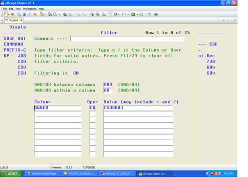
Use the TAB to move to
the first value box and enter your User ID.
For me, the line becomes
“OWNER EQ CSU0003” (without the
quotes). Then hit ENTER to set the
filter.
The screen below shows the Output Queue.
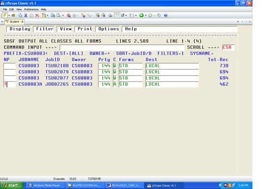
Select the job that you want to examine in a way similar to that in which you selected a file to edit. Tab down to the job that you are interested in examining and select it. There are a number of ways to select the job. The easiest way is to place a “?” (question mark) in the box (as shown above), and then hitting the ENTER key.
This leads to a display titled “SDSF JOB DATA SET DISPLAY”. Tab down to the line that is called PRINTER, enter an “S” in the box to select it and then hit the ENTER key. You should then see the output of your program.
If you do not see an entry called PRINTER, then your program had an error. In that case, you must hit F3 to return to the SDSF STATUS DISPLAY menu, select the job using the “S” command, and then examine the entire output. Note that this option shows quite a lot, including much that I cannot understand.
Find the text of your assembler program by hitting F8 a few times, and then look for error messages. While these may be hard to read, they do indicate the lines with problems.
Purging Jobs from the Hold Queue
From the ISPF Primary Option Menu, enter the two–character command “SD” (that is, no quotes) to access the SDSF system. As always, follow the command by hitting the Enter key. You may now examine the results.
Enter the command “O”, followed by the Enter key. Tab down to the job that you are interested in examining and select it in the same way you selected a file to edit.
Hit “P” and then the Enter key. If a selection box pops up, select option 3 and hit enter. This will purge the entry from the output queue.
NOTE: The display does not automatically update. Hit enter again to refresh the display.
Deleting Files
From main menu, go to option 3 (Utilities), then option 1 (Libraries). You will see a screen labeled Library Utility. Note the grouping in the middle of the screen, titled ISPF Library. It specifies Project, Group, and Type. On my screen, the values are what I want.
Hit enter. You will see a list of your files. Tab to the file, place a D in the line, hit enter and then confirm. Here I have chosen to delete the file LAB01.
Leaving the System.
Hit F3 repeatedly to get back to the main menu from either the Editor or the SDSF.
Enter the one–character command “X” to exit. You may be prompted by a menu
“Specify Disposition of Log Data Set”. I
always choose option 3
“Keep Data Set – Same”.
Then you will see a blank screen, similar to the one that you saw after typing “L TSO” at the start of the session. Enter the string “LOGOFF”, assuming that you want to log off.
Disconnect from the mainframe by selecting the File menu and then Disconnect.
Close the Windows application that serves as the terminal emulator.
Creating and Editing a Program
We now discuss the process of
entering a program into the editor. One
way, discussed below, is to use the Insert mode and enter all of the text
manually. The option that we shall elect
involves fall less manual work. There
are two procedures discussed next.
1. How to get a copy of the first program.
2. How to use that copy to create editable copies for your
future programs.
Getting a Copy of the
First Program
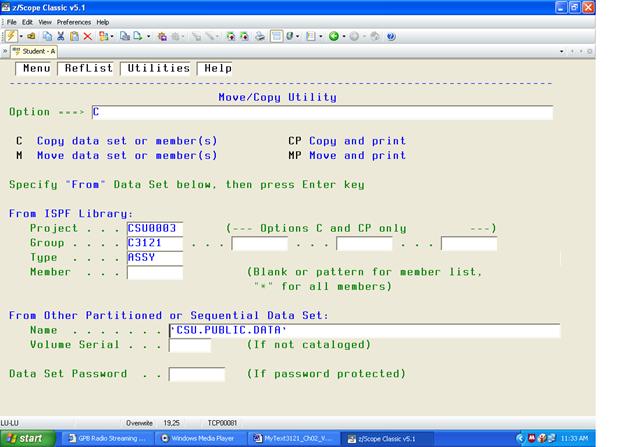
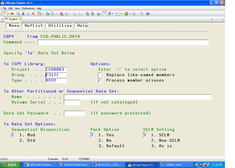
The text of the first program is stored in a public library. In order to get the copy, you must start from the ISPF PRIMARY OPTIONS MENU. Select Option 3 for the Utilities Menu and then select Option 3 again, to get to the Copy/Move menu. The option is “C” for COPY.
Enter the “C” in the options
line, but do not hit the ENTER key. Use the TAB key to move to the box labeled
“Name” in the section labeled “From Other Partitioned or Sequential Data
Set”. Enter ‘CSU.PUBLIC.DATA’
along with the single quotes. Hit the
ENTER key after you do this.
After this, you will be presented with a similar screen for the “To Data Set”
This is what I want; it lists my
project, group, and type correctly. I
just hit ENTER.
This brings me to the file COPY menu.
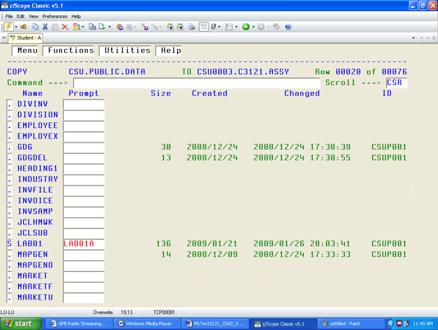
Here I have used the F8 key to move to the display containing the file I wanted and the TAB key to move to the actual file. It is LAB01. In the Prompt box, I enter a name to use if I do not want to call it “LAB01” and then hit enter.
After this, the file should be in your area and available for editing. Again, go back to the ISPF PRIMARY MENU, and select Option 2 for editing. You will see the Edit Entry Panel.
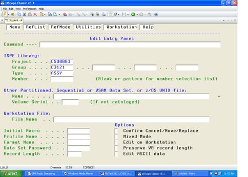
You may enter your file name in the Member Box or just hit enter to get.
To edit LAB01A, I just TAB to the box on the left of the name and hit ENTER.
You should not add any text directly to LAB01. It is the “boilerplate” for all the labs that follow. You should assemble and run it to show that it works. It is a basis for future labs.
Generating New Files from LAB01
As an example, suppose I want to generate a file called LAB02, which will be based on the existing file LAB01. It will use all of the standard “boilerplate” code from LAB01.
Go to the Edit Entry Panel, and select a new file name.
ISPF Library
Project CSU0003__
Group ASM______
Type SRC_____
Member LAB02_____
Hit ENTER to get the editor with a new blank file.
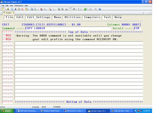
In the command line enter COPY followed by the name of the file you want to copy. My file was named “LAB01A’, so I enter “COPY LAB01A”, without the quotes. I then hit ENTER.
At this point, it is important to change call occurrences of the CSECT name to whatever you want to use. The computer will not care if you name everything “LAB01”, but I shall.
IMPORTANT AND URGENT
I am showing you an example of a fully functional program
with my User ID.
You MUST change the User ID in the first line to your own, or you will run in
my account.
If I find any of your programs in my Project, I shall delete them without
reading them.
The Dual–Mode Editor
This editor is a classic “dual
mode” editor, with an Insert mode and a Command mode.
The Insert Mode is used to enter
lines of text into your program.
When you
start the editor, it is in the Command mode.
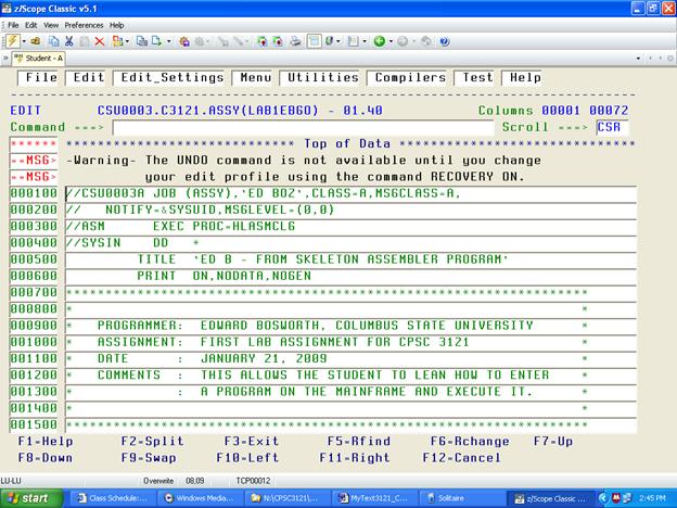
Here is my display when I select LAB1 and start the editor. There are several things to note before we
start the edit.
1. Note
the CSU0003A. This is my USER ID with an arbitrary letter
appended.
You MUST use your own User
ID.
2. The two lines beginning with “—MSG>” can be ignored.
In command mode, one repeatedly uses the TAB key to move up
and down lines. In the way I have the editor set up; a number of TABs will get
me to the “000100” used as a line number.
The next TAB gets me, the next TAB gets me to the command line itself (the part
beginning with “//CSU0003A”. The next
TAB will move me to the line number “000200”.
Note that shift–TAB (holding the Shift Key while striking the TAB) moves the cursor backwards.
As an exercise, try to use the TAB
key to shift to the line below that at the bottom of the screen.
In this mode the tab moves to the top of the screen. Use the function keys to change screens.
In more modern terminology we have
the following identifications for the function keys
at the top of the modern keyboard.
F3 Exit the application, while saving the changes.
F7 Page up
F8 Page down.
Changing the Scroll Mode
There are two scroll modes “PAGE” and “CSR” (cursor). I prefer the cursor mode. To change from PAGE to CSR, tab over to the box following “Scroll ===>” and replace “PAGE” with the four–character string “CSR ”, including the trailing space to overwrite the final letter.
In cursor (CSR) mode, the F7 and F8 keys display the following
behavior:
F7 moves the line selected by the TAB to
the bottom of the screen
F8 moves the line selected by the TAB to
the top of the screen.
Inserting Text
To insert one or more lines of text, use the TAB or Shift–TAB to move the cursor to the line number of the line after which you want to insert text. Type “I” and then hit the enter key. I edited the image below, changing the color of the “I” to emphasize it.
You should now be in Insert Mode. Enter each line of text followed by a CR as needed.
To exit Insert Mode, enter a blank line by just hitting the CR
with no text on the line.
This should return you to Command Mode.
The only way to insert blanks is to use the space bar. Do not use the “®” arrow key, as that will just move the cursor without inserting anything. The line will appear to have spaces inserted, but in reality it will not. This can be verified by saving the file, closing the editor, and reopening it.
Deleting a Line
To delete a line, use the TAB or Shift–TAB to move the cursor to the line number preceding the line to delete, hit the “D” key, and then hit the enter key. The line should be deleted. Once again, I have edited the image and changed the color of the “D” to highlight it.
Rare Editor Commands
In certain instances of the assembly process, it is important
to place text in the correct column.
In that case, one might want a guide to the columns. This is not like the old days of punch cards
when one could examine the card and read the column number.
To view the columns, type COLS on the line that one wants to
inspect and hit Enter.
Don’t forget to delete the COLS line when done.
This figure shows that the “X” continuation character has been correctly placed in column 72.
HEX
These two commands are typed on the command line of the editor. In the HEX mode, the
editor will show the hexadecimal value of every character in the line, in two
rows below.
To view the hexadecimal equivalents (EBCDIC code) for the text
characters, enter the
command “
The output from the HEX ON will be verbose. In its typical use, this mode is used to search for undesired non–printable characters. In the three lines below, we see that the only non–printable character is the space, which has EBCDIC code 0x40.
Running with Output to
Disk
To output to file SP2008.LAB1OUT in your user area, replace the GO.PRINTER line with
//GO PRINTER DD
DSN=KCNNNNN.SP2008.LAB10UT,SPACE=(TRK,(1,1),RLSE),
// DISP=(NEW,CATLG,DELETE)
Neither the name “SP2008” nor the name “LAB1OUT” can exceed eight characters in length.
Viewing the Output Disk
File
From the main menu, enter the four character string “=3.4” and hit ENTER twice.
Find the output file by using the F7 and F8 keys as well as the TAB key.
There are two ways to examine this file.
S Place S by the file name and hit ENTER. This will show the file attributes.
E Place E by the file name and hit ENTER twice. The text of the file should display.