It is possible to use labels defined in the body of the program as default values.
MACRO
DIVID2 "=MPG,&DIVIDEND=,&DIVISOR=
ZAP &QOUT,&DIVIDEND
DP
",&DIVISOR
MEND
With this definition, the two invocations are exactly equivalent.
DIVID
MPG,MILES,GALS
DIVID2 &DIVIDEND=MILES,&DIVISOR=GALS
The invocation of the macro DIVID2 will expand as follows:
ZAP MPG,MILES
DP
MPG,GALS
Having reviewed the syntax of keyword macros, we now turn to the main topic of this chapter: a brief discussion of the Input/Output Control System and associated macros. Following the lead of Peter Abel [R_02], the focus will be on the following:
DCB Data Control Block, used to define files.
OPEN This makes a file available to a program, for either input or output.
CLOSE This
terminates access to a file in an orderly way.
For a buffered output
approach, this
ensures that all data have been output properly.
GET This makes a record available for processing.
PUT This
writes a record to an output file. In a
buffered output, this may
write only to an
output buffer for later writing to the file.
Register Usage
Each I/O macro that we shall discuss expands into a sequence of calls to operating system routines, most probably in the LIOCS (Logical I/O Control System) level. For this reason, we should review the general–purpose registers used by the operating system.
0 and 1 Logical
IOCS macros, supervisor macros, and other IBM
macros use
these registers to pass addresses.
13 Used
by logical IOCS and other supervisory routines to hold the
address of a
save area. This area holds the contents
of the user
program’s
general purpose registers and restores them on return.
14 and 15 Logical
IOCS uses these registers for linkage. A
GET or PUT
will load
the address of the following instruction into register 14
and will
load the address of the actual I/O routine into register 15.
This use of
registers 13, 14, and 15 follows the IBM standard for
subroutine
linkage, which will be discussed in a later chapter.
One “take away” from this discussion is the fact that user programs should reference and use only registers 3 through 12 of the general–purpose register set. Some general–purpose registers are less “general purpose” than others.
Record Blocking
In IBM terminology, a data set is a collection of data records that can be made available for processing. The term is almost synonymous with the modern idea of a disk file; for most of this text the two terms will be viewed as equivalent. One should realize that the idea of a data set is more general than that of a disk file. Data sets can be found on a DASD (Direct Access Storage Device, either a magnetic disk or a magnetic drum), on magnetic tape, or on a sequence of paper punch cards. The term “data set” is a logical construct.
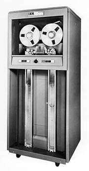
In order to understand the standard forms of record organization, one must recall that magnetic tape was often used to store data. This storage method had been introduced in the 1950’s as a replacement for large boxes of punched paper cards. The standard magnetic tape was 0.5 inches wide and either 1200 or 2400 feet in length. The tape was wound on a removable reel that was about 10.5 inches in diameter. The IBM 727 and 729 were two early models.
The IBM 727 was officially announced on September 25, 1963 and marketed until May 12, 1971. The figure at left was taken from the IBM archives, and is used by permission.
It is important to remember that the tape drive is an electro–mechanical unit. Specifically, the tape cannot be read unless it is moving across the read/write heads. This implies a certain amount of inertia; physical movement can be started and stopped quickly, but not instantaneously.
One physical manifestation of this problem with inertia is the inter–record gap on the magnetic tape. If the tape contains more than one physical record, as do almost all tapes, there must be a physical gap between the records to allow for starting and stopping the tape. In other words, the data layout on the tape might resemble the following:

One issue faced early by the IBM design teams was the percentage of tape length that had to be devoted to these inter–record gaps. There were several possible solutions, and each one was pursued. Better mechanical control of the tape drive has always been a good choice.
Another way to handle this problem would be to write only large physical records. Larger records lead to a smaller percentage of tape length devoted to the inter–record gaps. The efficiency problem arises with multiple small records, such as images of 80–column cards.

One way to improve the efficiency of storage for small records on a magnetic tape is to group the records into larger physical records and store these on tape. The following example is based on the one above, except that each physical record now holds four records. Note the reduction of the fraction of tape length devoted to inter–record gaps.
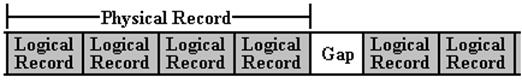
This process of making more efficient use of tape storage is called record blocking. The program reads or writes logical records that have meaning within the context of that program. These logical records are blocked into physical records for efficiency of storage. In a particular data set, all physical records will contain the same number of logical records; the blocking factor is a constant. The only exception is the last physical record, which may be only partially filled.
Consider a
set of 17 logical records written to a tape with a blocking factor of 5. There would be four physical records on the
tape.
Physical record 1 would contain
logical records 1 – 5,
physical record 2 would contain
logical records 6 – 10,
physical record 3 would contain
logical records 11 – 15, and
physical record 4 would contain
logical records 16 and 17.
On a physical tape, it is likely that the last physical record will be the same size as all others and be padded out with dummy records. In the above example, physical record 4 might contain two logical records and three dummy records. This is a likely conjecture.
Magnetic tape drives are not common in most computer systems these days, but the design feature persists into the design of the modern data set.
Use of the I/O Facilities
In order to use the data management facilities offered by the I/O system, a few steps are necessary. The program must do the following:
1. Describe
the physical characteristics of the data to be read or written with respect to
data set organization, record
sizes, record blocking, and buffering to be used.
2. Logically connect the data set to the program.
3. Access the records in the data set using the correct macros.
4. Properly
terminate access to the data set so that buffered data (if any)
can be properly handled before
the connection is broken.
While some of these steps might be handled automatically by the run–time system of a modern high–level language, each must be executed explicitly in an assembler program.
Style Conventions for Invoking I/O Macros
Some of the I/O macros, especially the file definition macro, require a number of parameters in order to specify the operation. This gives rise to a stylistic convention designed to improve the readability of the program. The most common convention used here is to use the keyword facility and list only one parameter per line.
While one possibly could use positional parameters in invoking an I/O macro, this would require any reader to consult a programming reference in order to understand what is intended. Of course, it is possible for a programmer to forget the proper argument order.
Here is a file definition macro invocation written in the standard style.
FILEIN DCB DDNAME=FILEIN, X
DSORG=PS,
X
DEVD=DA,
X
RECFM=FB,
X
LRECL=80,
X
EODAD=A90END, X
MACRF=(GM)
Note the “X” in column 72 of each of the lines except the last one. This is the continuation character indicating that the next physical line is a continuation of the logical line. To reiterate a fact, it is the presence of a non–blank character in column 72 that makes the next line a continuation. Peter Abel [R_02] places a “+” in that column; that is good practice.
Here is another style that would probably work. It is based on old FORTRAN usage.
FILEIN DCB DDNAME=FILEIN, 1
DSORG=PS, 2
DEVD=DA,
3
RECFM=FB, 4
LRECL=80, 5
EODAD=A90END, 6
MACRF=(GM)
Note that every line except the last has a comma following the parameter. This is due to the fact that the parameter string after the DCB should be read as a single line as follows:
DDNAME=FILEIN,DSORG=PS,DEVD=DA,RECFM=FB,LRECL=80,EODAD=A90END,MACRF=(GM)
The File Definition Macro
The DCB (Data Control Block) is the file definition macro that is most commonly used in the programs that we shall encounter. As noted above, it is a keyword macro. While the parameters can be passed in any order, it is good practice to adopt a standard order and use that exclusively. Some other programmer might have to read your work.
The example above shows a DCB invocation that has been shown to work on the particular mainframe system now being used by Columbus State University. It has the form:
Filename DCB DDNAME=Symbolic_Name, X
DSORG=Organization, X
DEVD=Device_Type, X
RECFM=Format_Type, X
LRECL=Record_Size, X
EODAD=EOF_Address, X
MACRF=(Input_Operation)
The name used as the label for the DCB is used by the other macros in order to identify the file that is being accessed. Consider the following pair of lines.
The example macro has one problem that might lead to confusion. Consider the line:
Filename DCB DDNAME=Symbolic_Name, X
The file name is the same as the symbolic name. This is just a coincidence. In fact it is the filename, which is the label associated with the DCB, that must match the other macros.
Here is an explanation of the above entries in the invocation of the DCB macro.
DDNAME identifies the file’s symbolic name, such as SYSIN for the primary system input device and SYSPRINT for the primary listing device. Here we use a slightly nonstandard name FILEIN, which is associated with SYSIN by a job control statement near the end of the program. That line is as follows:
//GO.FILEIN DD *
The “*” in this statement stands for the standard input device, which is SYSIN. This statement associates the symbolic name FILEIN with SYSIN.
DSORG
identifies the data set organization.
Typical values for this are:
PS Physical
sequential, as in a set of cards with one record per card.
DEVD defines a particular I/O unit. The only value we shall use is DA, which indicates a direct access device, such as a disk. All of our I/O will be disk oriented; even our print copy will be sent to disk and not actually placed on paper.
RECFM
specifies the format of the records. The
two common values of the parameter are:
F Fixed
length and unblocked
FB Fixed
length and blocked.
LRECL
specified the length (in bytes) of the logical record. A typical value would be
a positive decimal number. Our programs
will all assume the use of 80–column punched cards for input, so that we set LRECL=80.
BLKSIZE specifies the length (in bytes) of the physical record. Our sample invocation does not use this parameter, which then assumes its default value. If the record format is FB (fixed length and blocked), the block size must be an even multiple of the logical record size. If the record format is F (fixed length and unblocked), the block size must equal the logical record size. It is probably a good idea to accept the default value for this parameter.
EODAD is a parameter that is specified only for input operations. It specifies the symbolic address of the line of code to be executed when an end–of–file condition is encountered.
MACRF specifies the macros to be used to access the records in the data set. In the case of GET and PUT, it also specifies whether a work area is to be used for processing the data. The work area is a block of memory set aside by the user program and used by the program to manipulate the data. We use MACRF=(GM) to select the work area option.
The OPEN Macro
This macro opens the data set and makes its contents available to the program. More than one dataset can be opened with a single macro invocation. The upper limit on datasets for a single OPEN statement is 16, but that number would produce unreadable code. As a practical matter, your author would prefer an upper limit of two or three datasets for each invocation of the OPEN macro.
Consider the following two sequences of macro invocations. Each sequence does the same thing; it opens two datasets.
Sequence 1 is a single statement.
OPEN
(FILEIN,(INPUT),PRINTER,(OUTPUT))
Sequence 2 has two statements, which could appear in either order.
OPEN (FILEIN,(INPUT))
OPEN (PRINTER,(OUTPUT))
Each of these statements assumes that the two Data Control Blocks are defined.
FILEIN DCB
Define the input file here
PRINTER DCB Define
the output file here
The general format of the OPEN macro for one file is as follows [R_21, page 67].
[LABEL] OPEN
(ADDRESS[,(OPTIONS)]
Multiple files can be opened at the same time, by continuing the argument list.
[LABEL] OPEN
(ADDRESS1[,(OPTIONS1),ADDRESS2[,(OPTIONS2)]
Note that the first argument for opening the dataset is the file name used as the label for the DCB that defines the dataset. This is the label (address) associated with the DCB, not the symbolic name of the file (SYSIN, SYSPRINT, etc.).
It is also possible to pass the address of the DCB in a general–purpose register. When a register is used for this purpose, it is enclosed in parentheses. Here are two equivalent code sequences, each of which opens FILEIN for INPUT.
*
OPTION 1
OPEN (FILEIN,(INPUT))
*
* OPTION 2
LA R2,FILEIN
OPEN ((2),(INPUT))
Note the parentheses around the second argument in each of the two individual invocations of the OPEN macro. This is a use of the sublist option for macro parameters [R_17, p. 302]. A sublist is a character string that consists of one or more entries separated by commas and enclosed in parentheses. What is happening here is that the macro definition is written for a sublist as a symbolic parameter, and this is a sublist of exactly one item.
There is one advantage in creating a separate OPEN statement for each file to be opened. If the macro fails, the line number of the failing statement will be returned. With only one file per line, the offending file is identified immediately.
The Close Macro
This macro deactivates the connection to a dataset in an orderly fashion. For output datasets, this will flush any data remaining in the operating system buffers to the dataset, so that nothing is lost by closing the connection. If needed, this macro will update any catalog entries for the dataset; in the Microsoft world this would include the file attributes.
Once a dataset is closed, it may be accessed again only after it has once again been opened.
While it may be possible to execute a program and terminate the execution without issuing a CLOSE for each open file, this is considered very bad programming practice.
The general format of the CLOSE macro for one file is as follows [R_21, page 27].
[LABEL] CLOSE (ADDRESS[,(OPTIONS)]
Multiple files can be closed at the same time, by continuing the argument list.
[LABEL] CLOSE
(ADDRESS1[,(OPTIONS1),ADDRESS2[,(OPTIONS2)]
The code
that has been successfully used in our lab assignments seems not to be of
this form. Here are the lines that we
have used to close the INPUT and PRINTER.
A90END CLOSE
FILEIN
CLOSE
PRINTER
The format above is that preferred for use when running under the DOS operating system, which is an IBM product not related to the better known Microsoft product. Our programs are run under a variant of the OS operating system. According to the standard format for OS, the above statements should have been written as follows.
A90END CLOSE (FILEIN)
CLOSE (PRINTER)
Apparently, either form of the CLOSE macro for a single file will work.
When closing more than one file with a single CLOSE macro, one must allow for the fact that the options do exist, even if not commonly used. Here is the proper format.
A90END
CLOSE (FILEIN,,PRINTER)
Notice the
two commas following FILEIN. This
OPTIONS1
is not used. Were only one comma
present, the assembler would try to interpret the string PRINTER as an option
for closing FILEIN. The
lack of options following the string PRINTER
Locate Mode
The next two system macros to be discussed are GET and PUT. Before discussing either of these, it is important to note an I/O mode that will not be discussed here. This is called “locate mode”; it allows direct processing of data in the system buffers, so that the program need not define a work area. As this is a very minor advantage [R_02, page 262], we shall omit this feature and assume that each GET and PUT references a work area.
The GET Macro
This macro makes available the next record for processing. The record input overwrites the previous contents of the input area. There are two general formats as used with a work area.
[label] GET
Filename,Workarea
[label] GET (1),(0)
In each of
these formats, the
In the
following examples, the file name is FILEIN and the work area is
GET
FILEIN,RECDIN
FILEIN DCB
Define the input file
RECDIN DS
CL80 This is the input work
area
The second uses the use of general–purpose registers 0 and 1 in the standard manner to store the addresses of the file definition area and the work area
LA 1,FILEIN
Address of the file definition
LA
0,RECDIN Address of the work
area
READIT
GET (1),(0) Read a record into RECDIN. Note the
standard use of the parentheses.
The PUT Macro
This macro writes a record from the output work area. There are two general formats.
[label] PUT
Filename,Workarea
[label] PUT (1),(0)
In each of
these formats, the
In the
following examples, the file name is PRINTER and the work area is
PUT
FILEIN,RECDIN
PRINTER DCB
Define the input file
DATOUT
DS
CL133 This is the output work
area
The second uses the use of general–purpose registers 0 and 1 in the standard manner to store the addresses of the file definition area and the work area
LA 1,PRINTER
Address of the file definition
LA
0,DATOUT Address of the work
area
PUT (1),(0) Copy
data from work area to printer.
Expansion of the I/O Macros
47 OPEN
(PRINTER,(OUTPUT))
000014 48+ CNOP
0,4
000014 4510 C016 0001C 49+
BAL 1,*+8
000018 8F 50+ DC
AL1(143)
000019 000098 51+ DC
AL3(PRINTER)
00001C 0A13 52+ SVC
19
53 OPEN
(FILEIN,(INPUT))
00001E 0700 54+ CNOP
0,4
000020 4510 C022 00028 55+
BAL 1,*+8
000024 80 56+ DC
AL1(128)
000025 0000F8 57+ DC
AL3(FILEIN)
000028 0A13 58+ SVC
19
59 PUT
PRINTER,PRHEAD
00002A 4110 C092 00098 61+ LA
1,PRINTER
00002E 4100 C1A2 001A8 62+ LA
0,PRHEAD
000032 1FFF 63+ SLR
15,15
000034 BFF7 1031 00031 64+
ICM 15,7,49(1)
000038 05EF 65+ BALR
14,15
66 GET
FILEIN,RECORDIN
00003A 4110 C0F2 000F8 68+
LA 1,FILEIN
00003E 4100 C152 00158 69+
LA 0,RECORDIN
000042 1FFF 70+ SLR
15,15
000044 BFF7 1031 00031 71+
ICM 15,7,49(1)
000048 05EF 72+ BALR
14,15
95 A90END CLOSE (FILEIN)
000074 96+ CNOP
0,4
000074 4510 C076 0007C 97+A90END
BAL 1,*+8
000078 80 98+ DC
AL1(128)
000079 0000F8 99+ DC
AL3(FILEIN)
00007C 0A14 100+ SVC
20
101 CLOSE (PRINTER)
00007E 0700 102+ CNOP
0,4
000080 4510 C082 00088
103+ BAL 1,*+8
000084 80 104+ DC
AL1(128)
000085 000098 105+ DC
AL3(PRINTER)
000088 0A14 106+ SVC
20
116 PRINTER DCB
DSORG=PS,
DDNAME=PRINTER,
RECFM=FM,
LRECL=133
119+* DATA CONTROL BLOCK
120+*
000098 121+PRINTER
DC 0F'0' ORIGIN ON
122+* DIRECT ACCESS DE
000098 0000000000000000 123+
DC BL16'0' FDAD, DVTB
0000A8 00000000 124+ DC
A(0)
125+* COMMON ACCESS ME
0000AC 00 126+ DC
AL1(0) BUFNO, NUM
0000AD 000001 127+ DC
AL3(1) BUFCB, BUF
0000B0 0000 128+ DC
AL2(0) BUFL, BUFF
0000B2 4000 129+ DC
BL2'0100000000000000' DSO
0000B4 00000001 130+ DC
A(1) IOBAD FOR
131+* FOUNDATION EXTEN
0000B8 00 132+ DC
BL1'00000000' BFTEK, BFA
0000B9 000001 133+ DC
AL3(1) EODAD (END
0000BC 82 134+ DC
BL1'10000010' RECFM (REC
0000BD 000000 135+ DC
AL3(0) EXLST (EXI
136+* FOUNDATION BLOCK
0000C0 D7D9C9D5E3C5D940 137+
DC CL8'PRINTER' DDNAME
0000C8 02 138+ DC
BL1'00000010' OFLGS (OPE
0000C9 00 139+ DC
BL1'00000000' IFLGS (IOS
0000CA 0050 140+ DC
BL2'0000000001010000' MAC
141+* BSAM-BPAM-QSAM I
0000CC 00 142+ DC
BL1'00000000' OPTCD, OPT
0000CD 000001 143+ DC
AL3(1) CHECK OR I
0000D0 00000001 144+ DC
A(1) SYNAD, SYN
0000D4 0000 145+ DC
H'0' INTERNAL A
0000D6 0000 146+ DC
AL2(0) BLKSIZE, B
0000D8 00000000 147+ DC
F'0' INTERNAL A
0000DC 00000001 148+ DC
A(1) INTERNAL A
149+* QSAM INTERF
0000E0 00000001 150+ DC
A(1) EOBAD
0000E4 00000001 151+ DC
A(1) RECAD
0000E8 0000 152+ DC
H'0' QSWS (FLAG
0000EA 0085 153+ DC
AL2(133) LRECL
0000EC 00 154+ DC
BL1'00000000' EROPT, ERR
0000ED 000001 155+ DC
AL3(1) CNTRL
0000F0 00000000 156+ DC
H'0,0' RESERVED A
0000F4 00000001 157+ DC
A(1) EOB, INTER
158
****************************************
159 *
160 * INPUT FILE - DATA CONTROL BLOCK
161 *
162
****************************************
163 FILEIN DCB
DSORG=PS,
MACRF=(GM),
DEVD=DA,
DDNAME=FILEIN,
EODAD=A90END,
RECFM=FB,
LRECL=80
166+* DATA CONTROL BLOCK
167+*
0000F8 168+FILEIN DC
0F'0' ORIGIN ON
169+* DIRECT ACCESS DE
0000F8 0000000000000000 170+
DC BL16'0' FDAD, DVTB
000108 00000000 171+ DC
A(0)
172+* COMMON ACCESS ME
00010C 00 173+ DC
AL1(0) BUFNO, NUM
00010D 000001 174+ DC
AL3(1) BUFCB, BUF
000110 0000 175+ DC
AL2(0) BUFL, BUFF
000112 4000 176+ DC
BL2'0100000000000000' DSO
000114 00000001 177+ DC
A(1) IOBAD FOR
178+* FOUNDATION EXTEN
000118 00 179+ DC
BL1'00000000' BFTEK, BFA
000119 000074 180+ DC
AL3(A90END) EODAD (END
00011C 90 181+ DC
BL1'10010000' RECFM (REC
00011D 000000 182+ DC
AL3(0) EXLST (EXI
183+* FOUNDATION BLOCK
000120 C6C9D3C5C9D54040 184+
DC CL8'FILEIN' DDNAME
000128 02 185+ DC
BL1'00000010' OFLGS (OPE
000129 00 186+ DC
BL1'00000000' IFLGS (IOS
00012A 5000 187+ DC
BL2'0101000000000000' MAC
188+* BSAM-BPAM-QSAM I
00012C 00 189+ DC
BL1'00000000' OPTCD, OPT
00012D 000001 190+ DC
AL3(1) CHECK OR I
000130 00000001 191+ DC
A(1) SYNAD, SYN
000134 0000 192+ DC
H'0' INTERNAL A
000136 0000 193+ DC
AL2(0) BLKSIZE, B
000138 00000000 194+ DC
F'0' INTERNAL A
00013C 00000001 195+ DC
A(1) INTERNAL A
196+* QSAM INTERF
000140 00000001 197+ DC
A(1) EOBAD
000144 00000001 198+ DC
A(1) RECAD
000148 0000 199+ DC
H'0' QSWS (FLAG
00014A 0050 200+ DC
AL2(80) LRECL
00014C 00 201+ DC
BL1'00000000' EROPT, ERR
00014D 000001 202+ DC
AL3(1) CNTRL
000150 00000000 203+ DC
H'0,0' RESERVED A
000154 00000001 204+ DC
A(1) EOB, INTER